MoM singularities problems
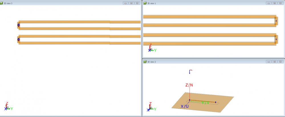
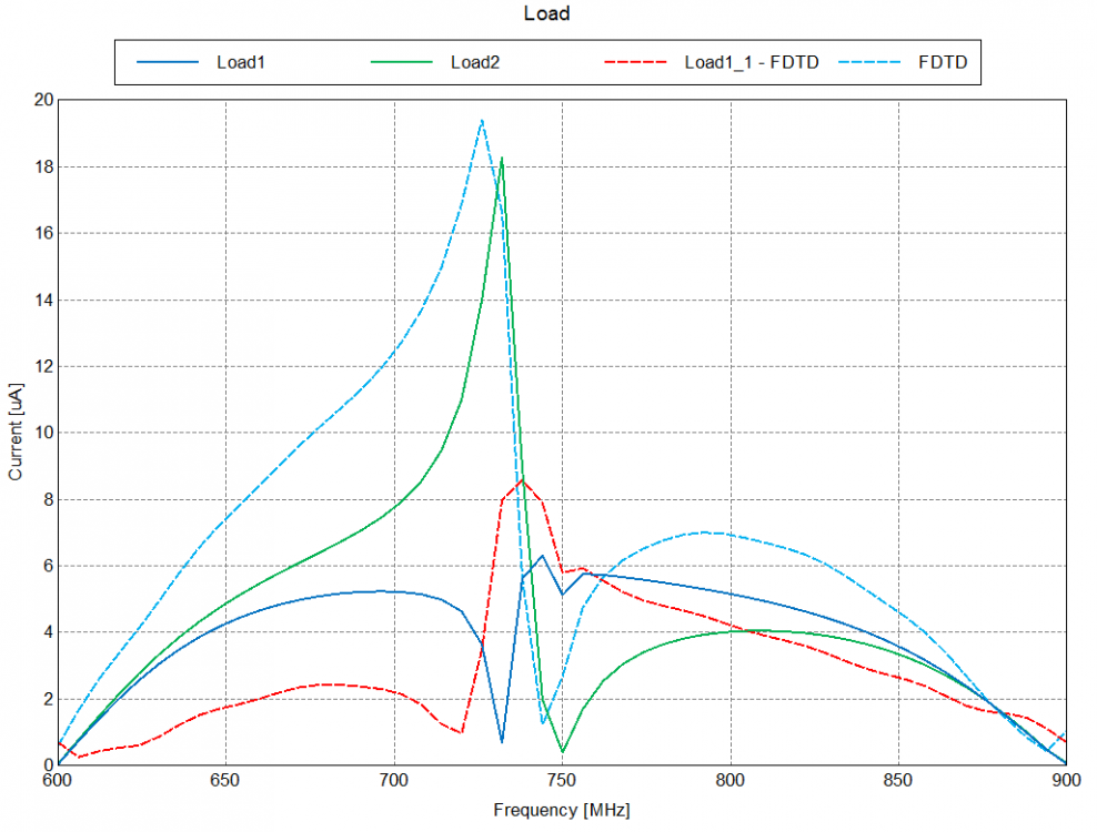
i have designed 4 transmission lines irradiated by plane wave, in which the electric field is parallel to the line. the obtained induced currents in each conductor contains distortions at the peaks.
i dont know where the distortion come from, i want to eliminate them. any suggestions. please
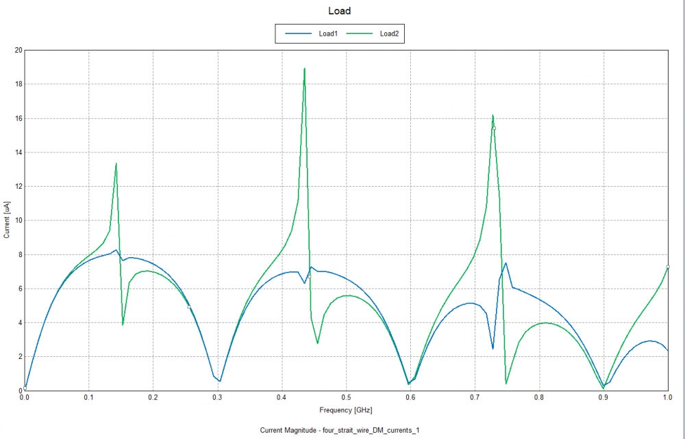
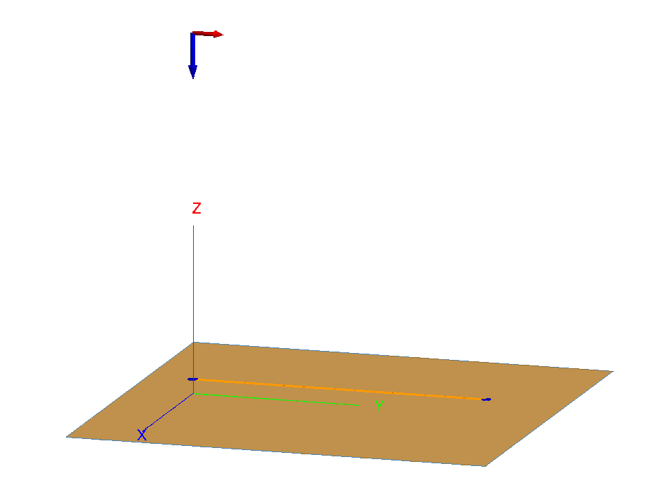
<?xml version="1.0" encoding="UTF-8"?>
Find more posts tagged with
Hello, JIF
the parameters of the design are :
h=50e -3 , sb=1.5e-3 , s=0.7e -3 , where the z components for each wire is h+sb+s, h+sb-s, h-sb+s, and h-sb-s . the wire lengths L=1 (units is ( m )) the loads ZL=100 ohm (all of them)
i have discovered one thing, if there is only two transmission lines, no distortions occurs. however, if another single transmission line is add to the first two, this distortion will occur again.
i want to thank you about your replay. i m very happy about your kindly replay, thank you so much.
i want to say that ___________________________________________________________
__________________________________________________________ ___________________________________________________________
Load Load Load Load
__________________________________________________ ____________________________________________________________
1- no distortion 2- there is distortion
note that, the electric field is parallel to the line as was shown in the first post.
thank you so much for your help
i m waiting your response.
i really i become so happy when i saw your post. It is very useful, thank you
hello
this is the model, it is constructed in FEKO suite 7.0
thank you in advance
hello
thank you so much for your help. the problem is that this distortion occurs only at the case when the electric field is parallel to the line, secondly the transmission line model cannot predict this resonance (the graph is smooth), also this resonance does not occur when there is only two wires above ground as explained above. i tried to modify the transmission line equations to obtain this resonance but i couldn't.
one question: is it possible to use FEM (Finite Element Method) to solve this problem ? or FDTD ?
thank you so much
i will try to find a solution
and i hope some one give us a complete explanation
thank you .
Remove the infinite ground. For the FDTD boundary set a PEC boundary at the bottom and the other ends of the bounding box keep on default.
You will need a fine mesh to ensure enough voxels due to the small wire-wire spacing.
I used a GPU, else the solution time would be a few hours. Memory was about 2.5 to 3.5 GB depending on the mesh.
hello@JIF
I want to tell you that the software FEKO and your suggestions have helped me to solve the problem that we have discussed above(about one year ago). As consequence, I have written a paper about this problem. this paper is just published in IEEE Transactions on Electromagnetic Compatibility, which is a very good journal. the paper link is
O. Gassab, L. Zhou, Z. Zhao and W. Yin, 'Effect of the Scattered Field on the Terminal Risers in Twisted-Wire Pairs With Floating Loads,' in IEEE Transactions on Electromagnetic Compatibility. https://ieeexplore.ieee.org/document/8600362
the resonance frequencies that appear in the DM response is due to the Scattered field effects that were neglected in the transmission line model. Now with this paper, the tranmission line model is improved.
thank you for your help, and your software FEKO is very amazing.
Oussama Gassab
Hello oussama1,
If you would like us to take a look, the best is to provide the model so that we can do investigations.
Since I don't see the model on the issue, I'll make suggestions for you to investigate.
As I said, if you provide the model, we can have a closer look.