Hi,
I was trying to do a Topology Optimization (min(comp) with a constrained volume frac). As a loadstep I wanted to use an intertia relief analysis.
The model consists of first order quad elements (meshsize =1 ) in a plate of 200 x 200 and the thick ness is 1 mm. The center of the plate is at x=y=z=0.
The load case is like the following:
<?xml version="1.0" encoding="UTF-8"?>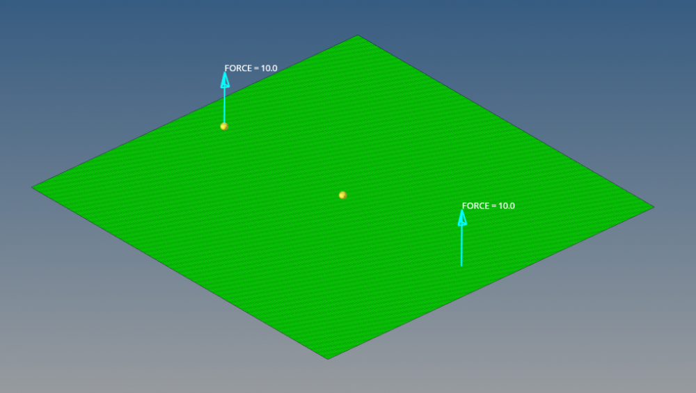
Now, I created the inertia relief card in ControlCards - PARAM and set it to -2 .... so I do not need to constrain the model and all should run well. The optimization steps are shown below.
Top left is the initial model which seems completely off to me... it has only mass at the loading points and that makes no sense does it?
I though, that it could be the low volume frac constraint I used (which is 0.15) ... I increased it to 0.5 and got the second result. Seems a lot better... Next I introduced some min and max member constraints. Min Member: 5, max Member 10.
As it tuned out, the model does not really converge into a 1/0 design.. so I tried a few things (which all failed): OptControl - Discrete=2, TopDisc = Yes ... decreased the force magnitude ... all with no effect. Finally with all those changes I also changed the Inertia Relief Parameter to -1 and created a Support1 constraint in the middle of the model... this also resulted in the same design as it can be seen below.
I finally made a Optimization with the inertia relief parameter set to 0... which is a constrained optimization, as the support1 constraint actually is a spc constraint and the movement ist blocked. The design looks a lot different.
<?xml version="1.0" encoding="UTF-8"?>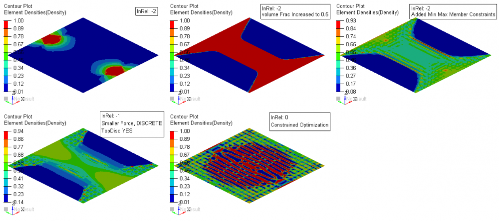
So my questions are:
- What am I doing wrong setting this up ? Is there an important point I am missing here? Can somebody who did something similar assist me here?
Thanks in advance and best regards!
Merula