Topology Optimization with Inertia Relief seems off ?!
Hi,
I was trying to do a Topology Optimization (min(comp) with a constrained volume frac). As a loadstep I wanted to use an intertia relief analysis.
The model consists of first order quad elements (meshsize =1 ) in a plate of 200 x 200 and the thick ness is 1 mm. The center of the plate is at x=y=z=0.
The load case is like the following:
<?xml version="1.0" encoding="UTF-8"?>
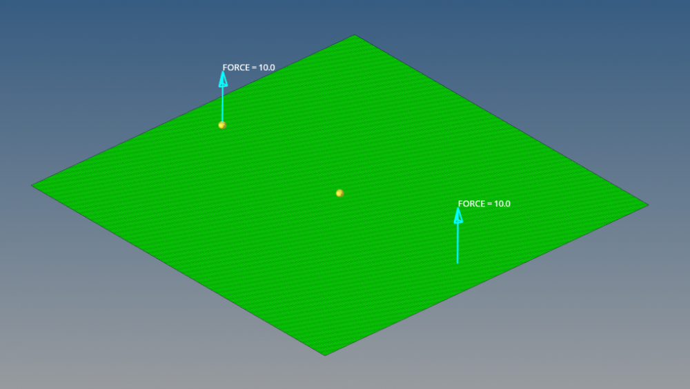
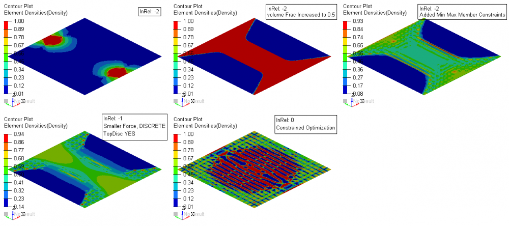
Now, I created the inertia relief card in ControlCards - PARAM and set it to -2 .... so I do not need to constrain the model and all should run well. The optimization steps are shown below.
Top left is the initial model which seems completely off to me... it has only mass at the loading points and that makes no sense does it?
I though, that it could be the low volume frac constraint I used (which is 0.15) ... I increased it to 0.5 and got the second result. Seems a lot better... Next I introduced some min and max member constraints. Min Member: 5, max Member 10.
As it tuned out, the model does not really converge into a 1/0 design.. so I tried a few things (which all failed): OptControl - Discrete=2, TopDisc = Yes ... decreased the force magnitude ... all with no effect. Finally with all those changes I also changed the Inertia Relief Parameter to -1 and created a Support1 constraint in the middle of the model... this also resulted in the same design as it can be seen below.
I finally made a Optimization with the inertia relief parameter set to 0... which is a constrained optimization, as the support1 constraint actually is a spc constraint and the movement ist blocked. The design looks a lot different.
<?xml version="1.0" encoding="UTF-8"?>
So my questions are:
- What am I doing wrong setting this up ? Is there an important point I am missing here? Can somebody who did something similar assist me here?
Thanks in advance and best regards!
Merula
Answers
-
Could you please share the .fem and .out file of the first run?
0 -
Hi @Merula
I think the topology results are as expected. With inertia relief the object is 'floating' and the stiffest design is the one where most material is near load application points, i.e. regions experiencing the most deformation.
The force magnitude has no effect on topology optimization minimum compliance results, but ratio between different loads does.
Try using DOPTPRM>DISCRETE to get better converged 0/1 design.
0 -
-
Thanks for the reply. I can see the logic, but how does it help when the solution is not connected to the 'SPC'... meaning the center of the model around which everything moves...
A little background: I try to model something like this: https://www.volocopter.com
And the solution to put mass everywhere where the motors are is not a valid solution for the frame /emoticons/default_wink.png' srcset='/emoticons/wink@2x.png 2x' title=';)' width='20' />
Thanks again for your replies.
Merula
0 -
Optimized solutions may seem counter-intuitive at first, but comparing baseline vs. optimized deformations, it can be seen the optimal topology does in fact minimize compliance. The solution does not get connected to 'SPC' in the middle, because it is not a constraint (no reaction forces) but a reference point. Adding non-structural mass (see bellow) will provide properly connected solution.
https://pdfs.semanticscholar.org/6e7c/9a0ba36d86ac73b3e2e213fa64e3b6c5b988.pdf
<?xml version="1.0" encoding="UTF-8"?>
I was expecting that optimizer will place material along regions of greatest strain energy (top left image). Adding concentrated mass in the middle produces expected topology (top right image, attached model). As you have already observed, 0.15 volume fraction is not enough material to connect load application points. I suspect stress singularity due to point loads is the reason why material is concentrated there. DUAL2 optimization algorithm produces better connected solution than DUAL. Eventhough DISCRETE=3 is not recommended for shells (upper bound is 2) it gives expected topology. TOPDISC+DISCRETE looks good, but it is infeasible design (volume fraction 0.43).
<?xml version="1.0" encoding="UTF-8"?>
0 -
Thank you very much for this. I will try to impliment this on my model and see where it goes from there.
0 -
Hello everyone,
I'm having some troubles when using inertia relief in my model. It is not constraining it at all and I am not understanding why.
The model is a formula student monocoque in CFRP and i'm using the option -2 of the inertia relief.
I created a post with more information and the models attached:
https://community.altair.com/community?id=community_question&sys_id=09668cf61b2bd0908017dc61ec4bcbf5Anyone knows what can be the problem?
Thanks,
Pedro Neves
0