A program to recognize and reward our most engaged community members
Hi guys,
do you have any ideas how to model an assembly with multiple composite components? As shown here http://www.rowlandcarson.org.uk/aviation/europa_435/_images/dscn1733.jpg I want to model ribs which are bonded to a specific surface. Do I have to do that with sub-laminates? Are there any tutorials for sub-laminate modeling?
I am using HW13.0
Thank you in advance.
Hi Wiko,
Check this link below:
http://www.altairuniversity.com/wp-content/uploads/2012/06/Composite_Pre_Postprocessing.pdf
Hi Prakash,
thank you for the presentation. I tried to realize the sample with a T-beam. The lay-up can be compared to the example, which can be found in the HW-Help (XXXX/Altair/13.0/help/hwsolvers/stack.htm?zoom_highlightsub=ply example 2). I have attached the .fem-file of my model and a short summary of the lay-up.
Actually, I have 4 sublaminates and an interfacelaminate to 'bond' all sublaminates together. I have assigned PCOMPP-property to all mesh-elements. After modeling, I have started a short analysis of the beam but the following error-msg appeared:
*** ERROR # 640 *** STACK 5 is incorrectly or ambiguously defined. This could be due to disconnected substacks, duplicate interfaces or inconsistent interfaces orientations. Please verify the substacks and interfaces thoroughly.
Can you give me a feedback with hints to solve this problem? Another question is, does the geometry have to be 'connected together' for modeling a laminate with sublaminates?
Best regards
Wiko
Unable to find an attachment - read this blog
I will have a look at the model and update to you soon.
thanks for sharing the file /emoticons/default_smile.png' srcset='/emoticons/smile@2x.png 2x' title=':)' width='20'>
Hi,
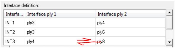
Just interchange the INT3 plies and everything should work fine /emoticons/default_smile.png' srcset='/emoticons/smile@2x.png 2x' title=':)' width='20'>
<?xml version="1.0" encoding="UTF-8"?>
Oh, I get it /emoticons/default_smile.png' srcset='/emoticons/smile@2x.png 2x' title=':)' width='20'> Thanks! Well does that mean that I have to build up the interface laminate according to the element normal? Like ply8 on the bottom and ply 4 as the second ply?
Well does that mean that I have to build up the interface laminate according to the element normal? Like ply8 on the bottom and ply 4 as the second ply?
Yes, exactly /emoticons/default_smile.png' srcset='/emoticons/smile@2x.png 2x' title=':)' width='20'>