Using connectors in Hypermesh

Hello and good afternoon,
I currently have a few problems using connectors in my Hypermesh-Simulation. I am trying to connect different parts of my model together via connectors to simulate the mechanical behaviour of a welded model.
The problem with my connectors is, that they are not transferring the load into other parts of my model. I think I set them up incorrectly. Is there any kind of tutorial on how to apply connectors?
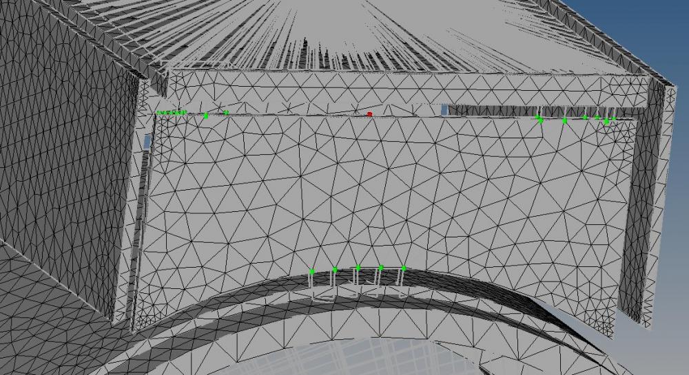
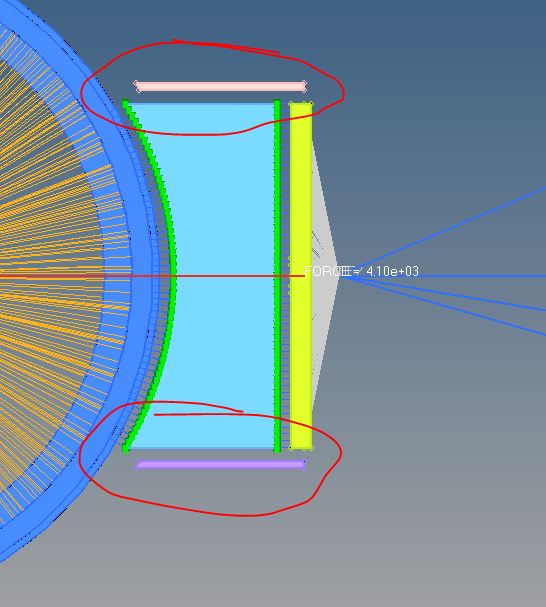
I attached a few pictures using different connectors. You will see that the parts of my model are set up with a distance of 2mm to each other. I tried using no distance first, but I could't not get the connectors to realize. Without a gap between the model parts they were always either yellow or red. Using a litte space between the parts could get the connectors to realize at least.
The only time I could get the applied loads to transfer was by using RBE2-elements and an unexploded model.
Many thanks
Steffen
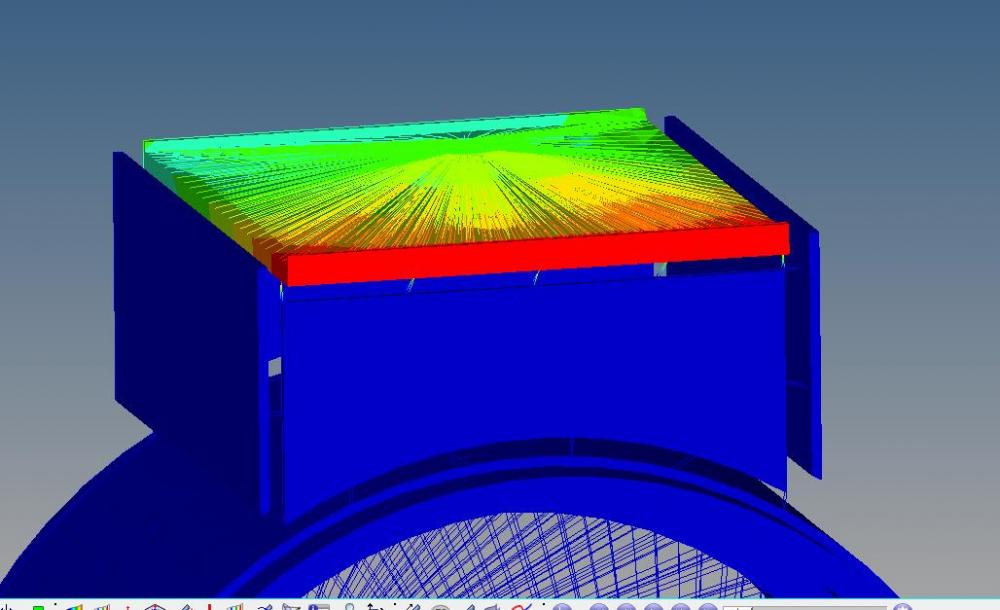
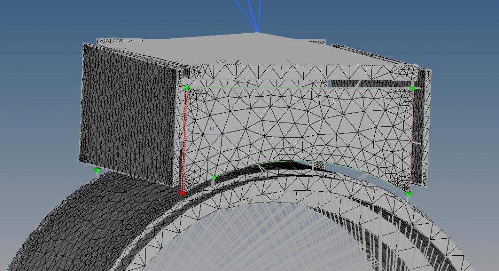
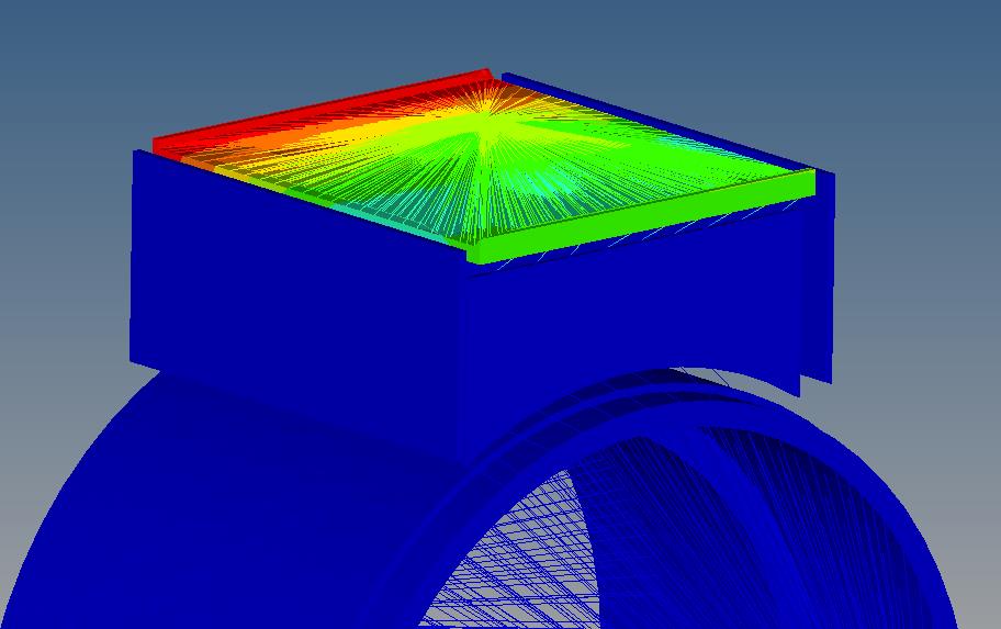
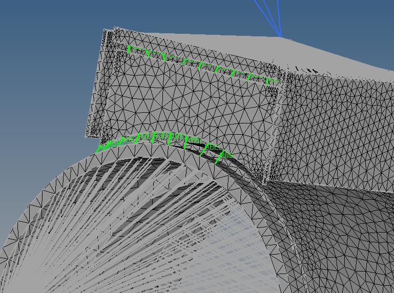
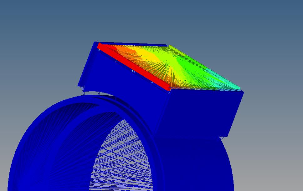
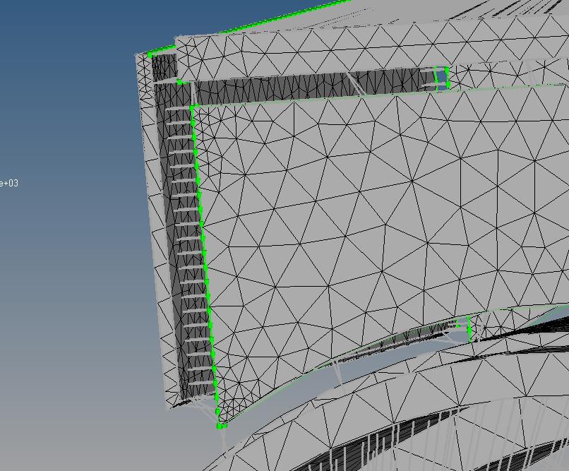
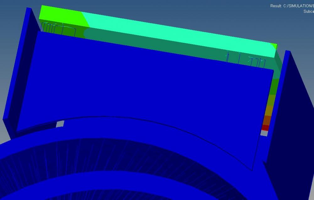
<?xml version="1.0" encoding="UTF-8"?>

Hi,
thank you very much. I attached my model to this post.

Hi Steffen,
Instead of PLOTTEL element type use WELD elements or BAR element type.
I see some of the parts are not connected.please connect it properly and then run.It model is properly connected with weld or rigid then only it will transfer load.
See attached screenshot.

I apologize for being so annoying, but changing the element type to 'weld' brought up another error message:
'
*** ERROR # 722 ***
An invalid rigid element.
This RBAR is not connected with any structural element.
RBAR element id = 124520
independent grid id = 30523
dependent grid id = 30524
Note: If this rigid element is also connected with other rigid elements,
then this error means that there is rigid body mode or mechanism remained
in this rigid element chain due to lack of connected structural elements.
'
Since I'm relatively new in the world of using Hyperworks programs, I'm not sure how to read the occurred problems out of the error messages.
I noticed that some the nodes are connected to different RBAR-lines, but even after deleting these, the problem remains the same.
But I guess it would still be an issue even after the first problem is fixed? Or do connectors behave differntly compared to 'normal' RBE-Elements?
I suggest to use RBE2 element and apply 1d checks like dependency and free nodes. As mentioned above connect part properly to avoid rigid body motion.
Regards
Rahul R

You have used SEAM connectors
please change to using SPOT connectors with elem type is WELD or RBE2/RigidLink/RBE3,...
Steffen,
The problem is coming from the type of element you are using to model the welds. In your base model you had PLOT elements which doesn't make sense. Instead use element types which transfers as Tinh and I suggested.

Hi,
Its possible to create spot weld for solid elements also.
Hi,
it's better to share your model.
there are several problems could occur in your model we cannot tell you detail.
so let us debug it after that we will tell you reason