🎉Community Raffle - Win $25

An exclusive raffle opportunity for active members like you! Complete your profile, answer questions and get your first accepted badge to enter the raffle.
Join and Win

Frequecy interval and reflection coefficient

User: "Altair Forum User"
Altair Employee
Updated by Altair Forum User

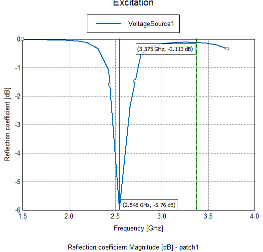
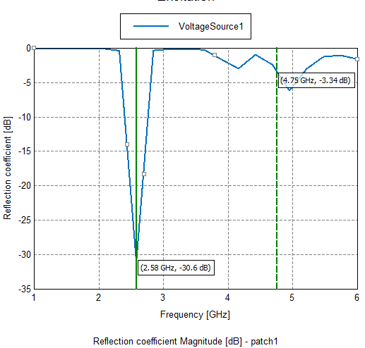
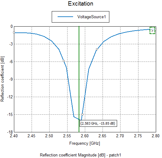
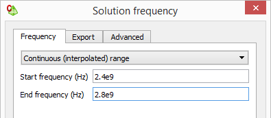
  Hi, I designed microstrip inset feed patch antenna but its reflection ceofficient changes with respect to frequency interval selection . Below,  there are 3 different frequency interval for the same design paramaters.

 Which parameter give me best results in fabrication or is there exist a rule to select frequecny interval to design antenna? What is the reason that cause this difference.


1.5-3.7.PNG.93b6b5fd49a04e39848d021aa5001e52.PNG1-6.PNG.4d105b7b4dfb8aaa660613d201ea1b90.PNG2.4-2.6.PNG.abe11fc680bc628d4d7a301611091afe.PNG

Find more posts tagged with

Sort by:
1 - 2 of 21
    User: "Johan_Huysamen"
    Altair Employee
    Updated by Johan_Huysamen

    Hi celaleddin taylan


    From your three images it looks like you have changed the frequency ranges, but kept the number of frequency samples the same. If you then reduce the range, you sample the frequency more finely.


    The behavior you see is caused by the fact that the number of discrete frequency samples is insufficient to locate the minimum reflection coefficient. More samples (finer sampling) is required.

    I would suggest that you try the 'Continuous (interpolated) range' option for the solution frequency:


    image.png


    With this option Feko will automatically sample a sufficient number ot frequency points to accurately locate the minimum value (at the resonance point).

    User: "Altair Forum User"
    Altair Employee
    OP
    Updated by Altair Forum User

    Thanks , it perfectly working all intervals.