🎉Community Raffle - Win $25

An exclusive raffle opportunity for active members like you! Complete your profile, answer questions and get your first accepted badge to enter the raffle.
Join and Win

Linear static analysis of plastic injection mold assembley

User: "Altair Forum User"
Altair Employee
Updated by Altair Forum User

Hi Rahul

I am doing linear static analysis on a plastic injection mold assembly. Clamping force and constraints are as following
<?xml version="1.0" encoding="UTF-8"?>2016-06-21_8-24-31.jpg
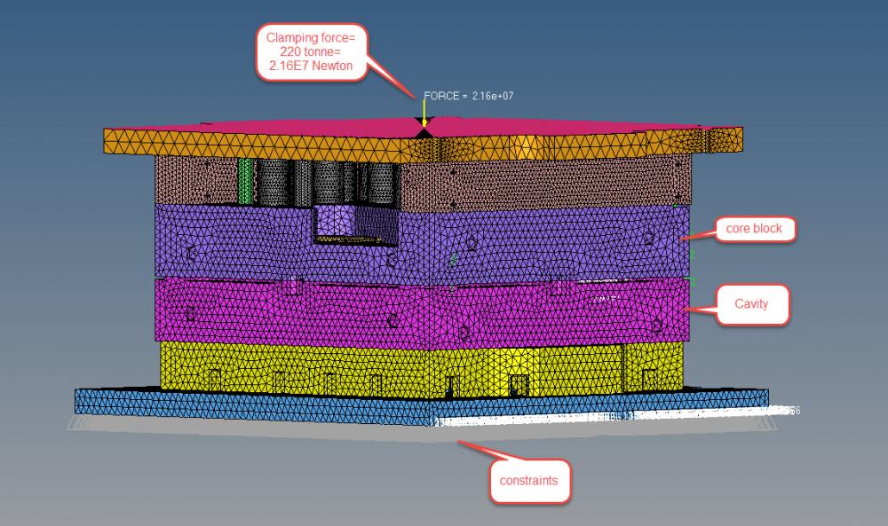
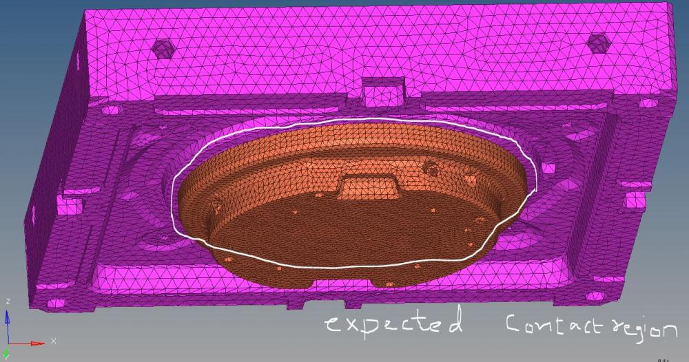
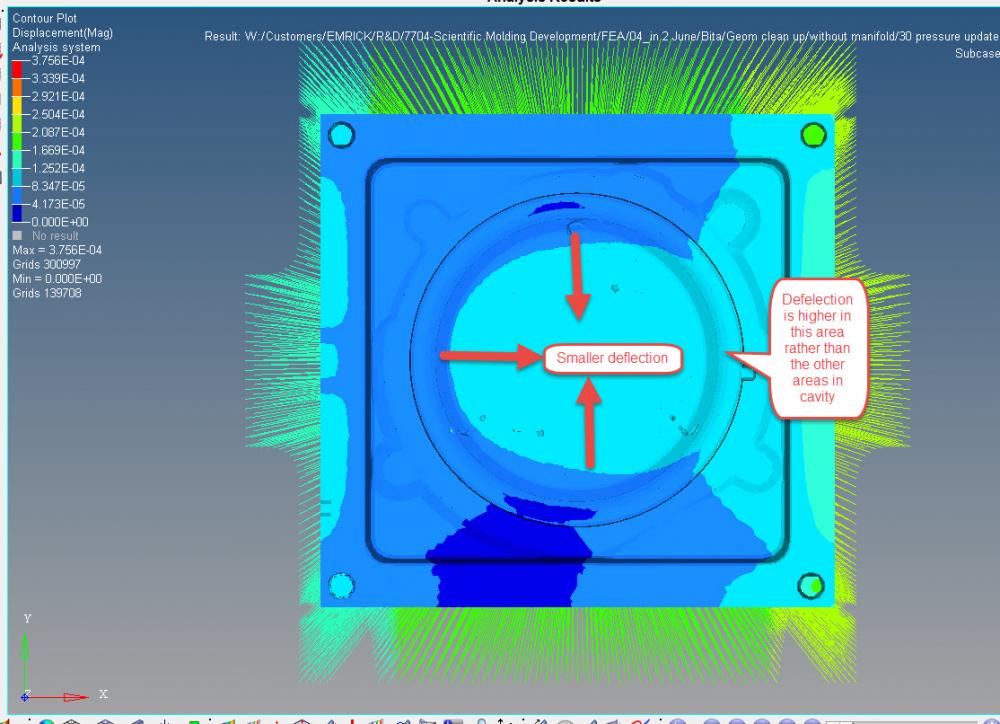
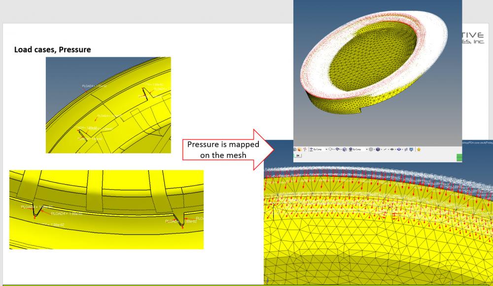
Pressure 54 MPa (This is the maximum pressure of molten plastic when it enters the cavity) is applied on core and cavity as shown below

<?xml version="1.0" encoding="UTF-8"?>2016-06-21_8-35-38.jpg
 
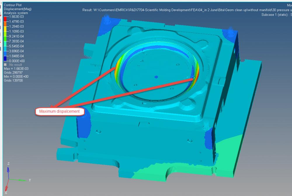
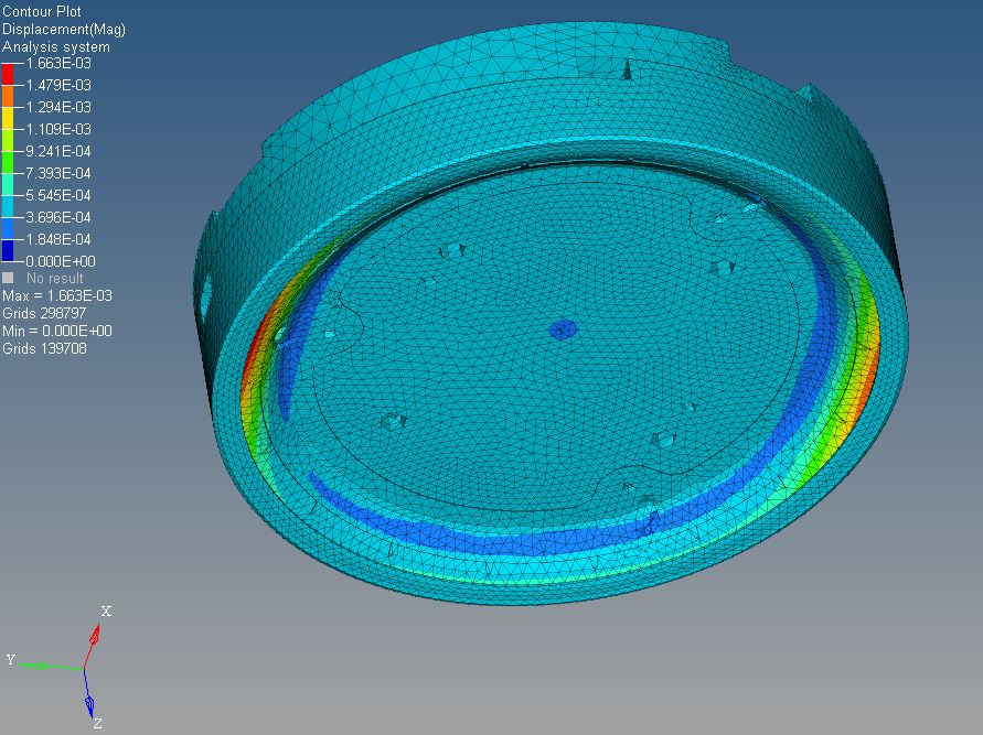
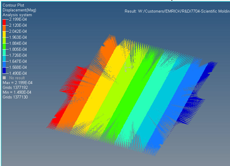
The problem is that, the maximum displacement is much more than what it should be in real case (It is almost 10 times more). I have used SI units and I checked material properties, units look right.
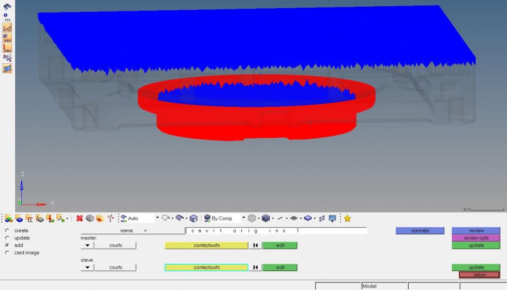
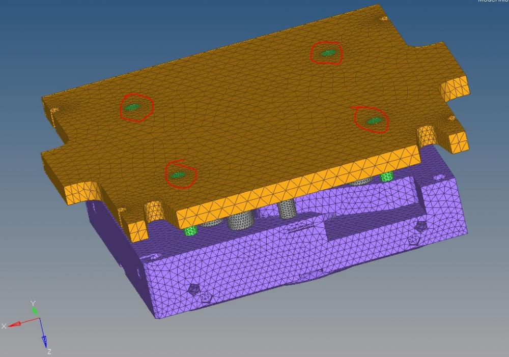
I don't know understand why I get this result. I have used bolt connection, RBE2 and also FREEZE contact to define connection between parts.
 

I sent you the model via your Dropbox link. I appreciate if you can spend some time and check my model and let me know what is the problem and why the maximum displacement I got is much more than the reality.Thanks a lot.

Find more posts tagged with

Sort by:
1 - 21 of 211
    User: "Altair Forum User"
    Altair Employee
    OP
    Updated by Altair Forum User

    Here you can see the maximum displacement if turn off components, Cavity, Top clamp plate and manifold plate in the assembly

    <?xml version="1.0" encoding="UTF-8"?>2016-06-21_10-09-42.jpg

    User: "Rahul Rajan_21763"
    New Altair Community Member
    Updated by Rahul Rajan_21763

    just downloaded file.Will check and update you.

    User: "Rahul Rajan_21763"
    New Altair Community Member
    Updated by Rahul Rajan_21763

    what is overall weight of entire model?

    User: "Altair Forum User"
    Altair Employee
    OP
    Updated by Altair Forum User

    Thanks alot


    I have to contact our customer and ask that

    User: "Altair Forum User"
    Altair Employee
    OP
    Updated by Altair Forum User

    It should be around 8336 kg

    User: "Rahul Rajan_21763"
    New Altair Community Member
    Updated by Rahul Rajan_21763

    Is that realistic?I mean 8336 kg is too much.

    User: "Altair Forum User"
    Altair Employee
    OP
    Updated by Altair Forum User

    It should be around 8336 kg


    I think the weight should be fine for a injection mold machine.


    Can you share the entire .out file here, please?

    User: "Rahul Rajan_21763"
    New Altair Community Member
    Updated by Rahul Rajan_21763

    When I post process output in Hyperview i see part name Origin ins1 deform more.See attached screenshot.


    When I try to check contact between cavity block & origin ins1 in Hypermesh while reviewing contact i found contact established in some other region.

    See attached screenshot for same.Please update contact and run again.I believe that was causing unexpected max displacement.

    <?xml version="1.0" encoding="UTF-8"?>origin ins1.JPG

    <?xml version="1.0" encoding="UTF-8"?>Expected conatct region.JPG

    <?xml version="1.0" encoding="UTF-8"?>Reviewing conatct.JPG

    User: "Altair Forum User"
    Altair Employee
    OP
    Updated by Altair Forum User

    Hi guys


    Thank you so much for your great help. You are right I missed that contact surface. I am going to create contact there and hopefully that would work.

    User: "Altair Forum User"
    Altair Employee
    OP
    Updated by Altair Forum User

    I fixed the connections and now I have more realistic results

    but there are still some issues. My model is almost symmetric but I don't understand why displacement distribution is not symmetric

    <?xml version="1.0" encoding="UTF-8"?>2016-06-22_16-26-14.jpg


    The second issue is that in the core block there are two regions that have lower thickness so it is expected that cavity pressure deforms those two regions more but the results are vice versa

    <?xml version="1.0" encoding="UTF-8"?>2016-06-22_16-32-08.jpg


    it is expected to have distribution of displacement something like the follwoing pic


    2016-06-22_16-40-59.jpg


    In real case flashing (leakage of molten plastic) happens at these two domains and our customer thinks it is because the thickness is lower in these two region, the structure is weaker and deformation is more. but  My last result shows opposite I appreciate if you can check my model and let me know the reason. I will upload the file via your drop box link.


    User: "Altair Forum User"
    Altair Employee
    OP
    Updated by Altair Forum User

    Hi,


    Is the load symmetric?

    User: "Altair Forum User"
    Altair Employee
    OP
    Updated by Altair Forum User

    yes the load is symmetric too


    User: "Altair Forum User"
    Altair Employee
    OP
    Updated by Altair Forum User

    Only Manifold plate is not symmetric

    2016-06-23_8-52-04.jpg

    User: "Altair Forum User"
    Altair Employee
    OP
    Updated by Altair Forum User

    that could be one of the reasons.


    what type of contacts have you used?

    User: "Altair Forum User"
    Altair Employee
    OP
    Updated by Altair Forum User

    I have used Freeze contact every where since I am doing linear static analysis

    User: "Altair Forum User"
    Altair Employee
    OP
    Updated by Altair Forum User

    Hi

    I was wondering if you had time to check my model. I am waiting for your reply

    User: "Altair Forum User"
    Altair Employee
    OP
    Updated by Altair Forum User

    Hi Bita,


    I don't have access to your model. But maybe you can check your self.


    Partition the components in to 4 symmetric parts and check their mass.

    User: "Rahul Rajan_21763"
    New Altair Community Member
    Updated by Rahul Rajan_21763

    I dont feel you entire model is symmetric& toget symmetric results it is recommended to have symmetric mesh.For second query i will check and update you.

    User: "Rahul Rajan_21763"
    New Altair Community Member
    Updated by Rahul Rajan_21763

    In real how this part are connected clamp plate & ejection pin.See attahced screenshot.

    <?xml version="1.0" encoding="UTF-8"?>Clamp plate and ejection pin.JPG

    User: "Altair Forum User"
    Altair Employee
    OP
    Updated by Altair Forum User

    The ejection pin are cylinder pin which goes inside clamp plate' holes.They are used for alignment only.

    User: "Altair Forum User"
    Altair Employee
    OP
    Updated by Altair Forum User

    Is this displacement contour correct for the rigid element? It is rigid but it has moved unevenly

    2016-06-28_8-40-13.jpg