Bell Crank Structure

 Altair Employee
Hello, I'm James Kim.
I have a trouble with putting my bell crank into hyperworks.
with line mesh wishbone, rigid (appropriate DOF setting for the situation), I make a realization of Bell Crank on hyperworks.
When I click the 'Optistruct', it has occur the problem. I think problem is rigid with no element like pic(bellhyper2).
I have no idea about how to make it looks like CATIA modeling.
How can I construct an object that is moving in one axis direction?
<?xml version="1.0" encoding="UTF-8"?>
<?xml version="1.0" encoding="UTF-8"?>
<?xml version="1.0" encoding="UTF-8"?>
Find more posts tagged with
Altair EmployeeIn this analysis, I'll constrain one part and apply force to the other in the vehicle.
and then I want to model t he bell crank to function properly in the direction of motion.
<?xml version="1.0" encoding="UTF-8"?>
<?xml version="1.0" encoding="UTF-8"?>
Thanks for sharing images. So you want to perform simple static analysis. Use beam element instead of CROD element. Generally orientation of beam element creates problem for this type structures. Please share .fem and .out file of the OptiStruct run.
Altair EmployeeActually, I did not reach the OptiStruct, so I just share the file about modeling.
and I have a another problem about missing surface.
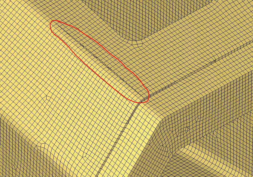
This image is the modeling file on CATIA and there is no empty betweent the surfaces.
<?xml version="1.0" encoding="UTF-8"?>
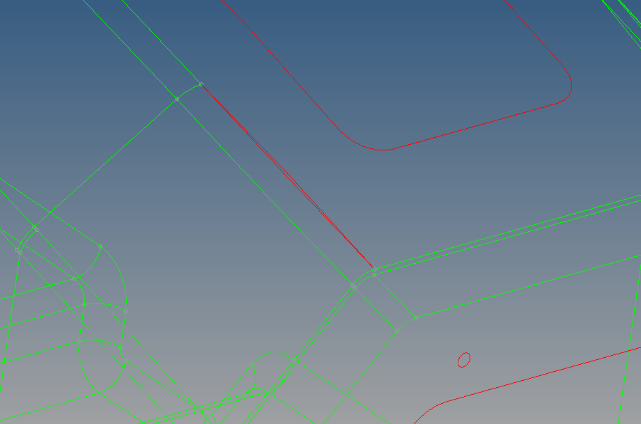
and this image is the imported file on Hypermesh and there is empty space between the surfacesl.
I can't select the surface for meshing.
How can I solve this problem?
If there is a empty space, I'm worried the result is expected to be different from normal.
I shared you my files, can you help me with these two situations?
Hi @James Kim
to repair surface geometry please use the Geom>edge edit>replace, specify proper tolerance and zoom in sufficiently to pick both free edges. This can also be done with toggle (in the same panel), but does not provide the same control.
Or you can repair after meshing by equivalence nodes (shift+F3):
Altair EmployeeThank you Ivan, I can solve the problem about surface
to Rahul R, Where can I check my filedrop to you? I lost my file all of them... TT
Hi James,
Please use below ftin link to download shared files.
https://ftin.india.altair.com:8443/message/8D5fOL56MUhUVSxAzJDJ6Y
Altair EmployeeThank you for your kindness..
Can I ask you again that the first question I asked is not solved yet.
For simulating same situation on CATIA model, I don't know exactly how to set dof of RBE2.
There is travel and stress following the Force in the condition of constraints.
If you know how to set this situation, can you give any advice?
I sent you hm file to secure file dropbox.
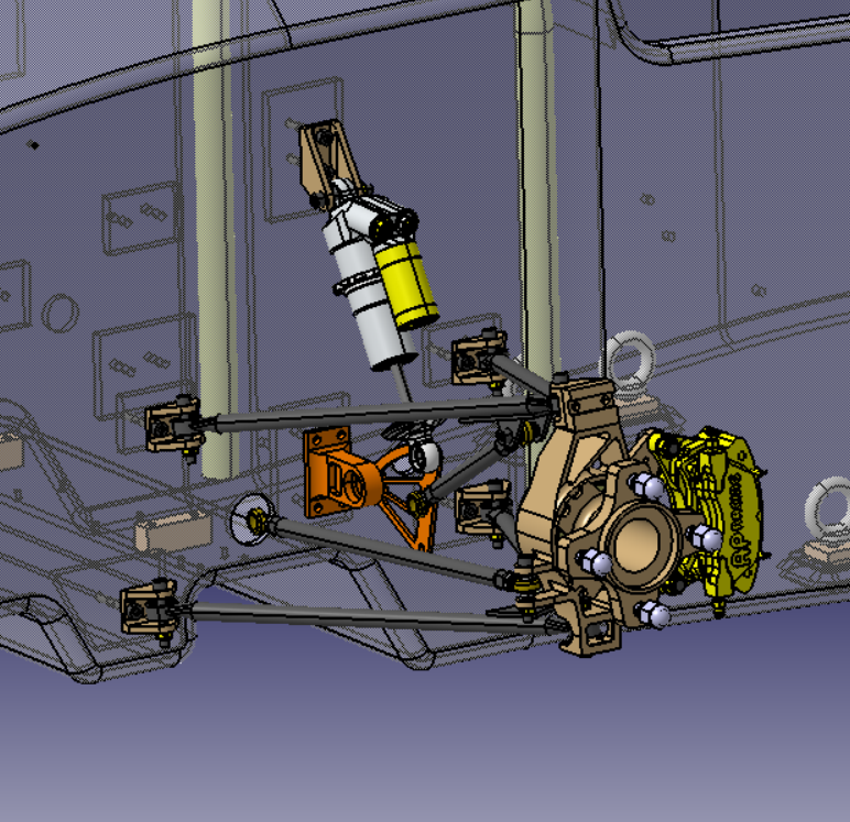
CAT model
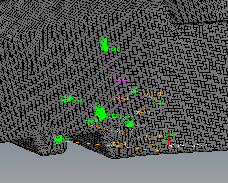
Condition of modeling on HYPERMESH
<?xml version="1.0" encoding="UTF-8"?>
Condition of modeling on HYPERMESH
<?xml version="1.0" encoding="UTF-8"?>
Condition of constraints on CATIA
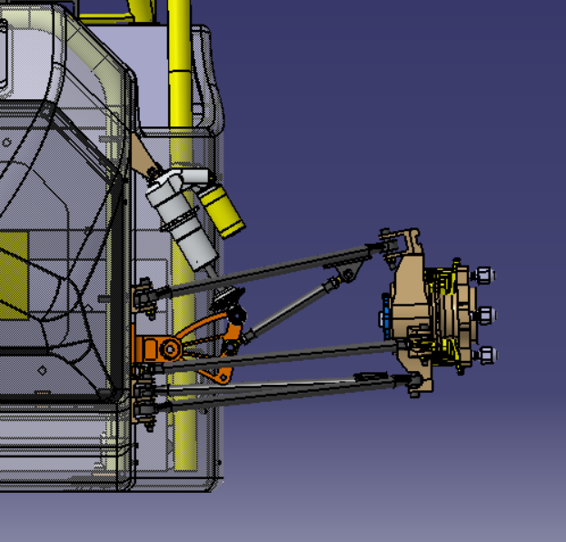
Before force on CATIA
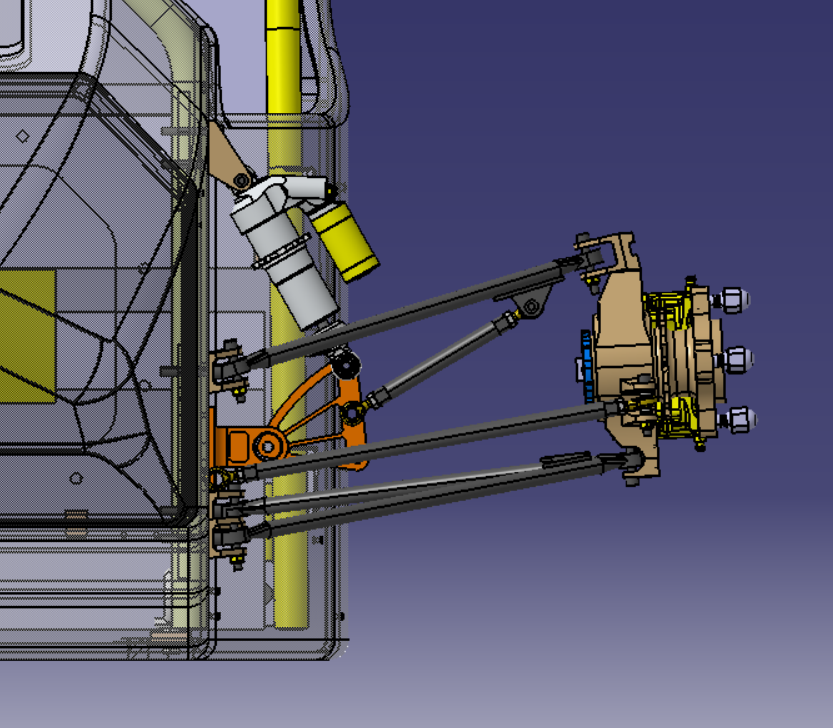
After force on CATIA
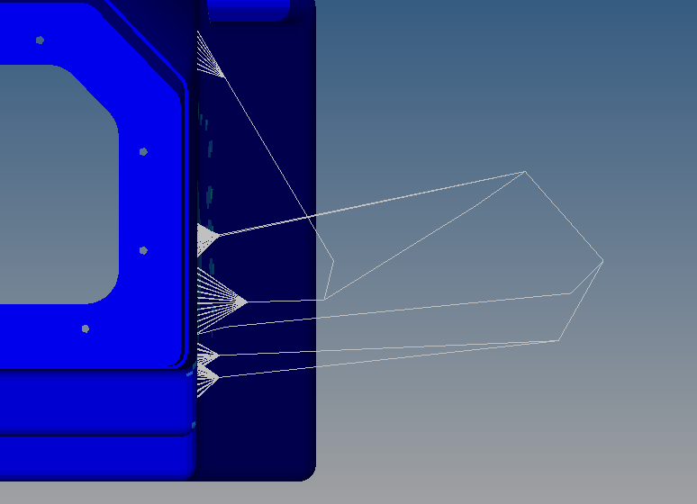
Before force on HYPERMESH
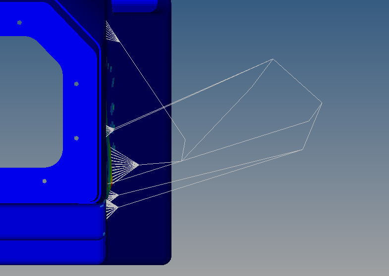
After force on HYPERMESH
Your shared hm file looks fine to me. Fix all dof for RBE2.I see modelling of back portion is still pending.
What is the objective of this analysis? You can explore Altair Inspire Motion features for such mechanism.
https://solidthinking.com/helpst/2019/inspire/en_us/GS_Motion.mp4