-
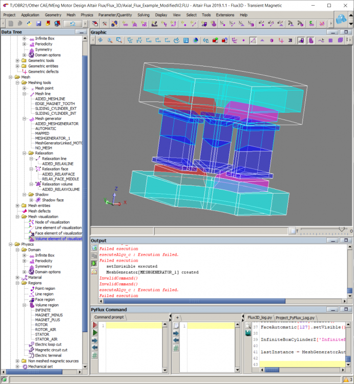
General data >> select mesh >> you have mesh point, line and generator. You can edit each point (line, generator) used by your device and change the proprieties
-
The second option, if you use an aided mesh you can also change the properties. To do it:
-
In the top select mesh >> aided mesh >> edit. You have the possibility to change the mesh information.
-
Thank you for your reply,
Is there a tutorial or manual which can guide me through editing a pre-made model/example, as i am struggling to remove the existing features and create another rotor and extend the current stator.
many thanks.
Hi
It is not something complicated, you just need to model one slot and one pole and define a mirror transformation. Then you just need to propagate the slot and pole.
you can use the example of tutorial and modify it.
In addition, in the modeler you can easily model the machine in 3D directly, or if you don not need to perform sensitivity analysis on the geometrical parameters, you can draw the model in any CAD software and import your model.
I hope this explanation helps you.
Best regards,
Mostafa
Thanks for the replies,
I have been able to use the symmetry function to mirror the axial flux example.
But i'm struggling to mesh the volumes of the model now with it taking over 24 hours and cannot reduce the mesh size, as an error appears. I think due to the mesh size getting to close to the air gap size.
Any Help would be appreciated.
Sam
Hi,
To reduce the mesh size in your device you can edit the mesh proprieties. To do it:
Best regards.
Hi,
As I told in my previous email, the problem come form the geometry. Hen I do check geometry Flux display an error message. There is an interference between the initial volumes and the new that you have created using a transformation. To avoid this type of the problem it is better if you use the modeler. I delete all the volumes that you have created, and I open the modeler context. To create the other volumes, I sued the symmetry par reference plan.
You will find attached the Flux project meshed. You need to check the physics if all the volumes are assigned to volume region.
Best regards.
Hi,
You are welcome.
I think the best way to get the torque Vs speed is when you create your solving scenario, you change the value of the speed. In the end of the solving you can draw a 3D curve (torque VS speed and time for example). If you want to draw the curve torque vs Speed, you can take a mean value of torque for each speed to do it you can use a macro: ExtractFrom3DCurve.PFM.
Best regards.
Hi,
In the first try to do it for one value of speed to be sur that you get a right curve of the torque (if it is not the case, check the phases, the current and shift angle).
You can use a magneto-static application to draw the curve torque Vs speed.
Best regards.
Thank You for your response,
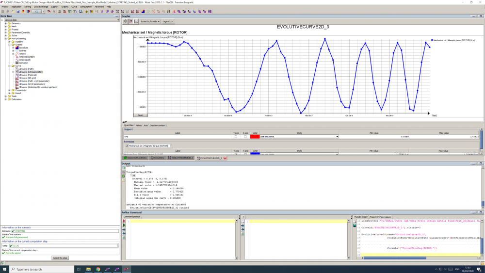
When i impose a constant 1000rpm, a constant positive torque, with a slight ripple as expected.
but when i change the Parameter I/O - SPEED, to TIME*100 the resulting Torque output now oscillates between 1 and -0.6.
Is there a way to fix this? and have a smooth torque curve.
If i try and achieve this by only editing the solving scenario, i can only control angle or position of rotor, not the speed.
Many Thanks
Hi,
For each operating point, you need to impose the value of the control angle (this allows to get the correct value of the torque). For this reason, in your case when you try to modify both speed and position and displays the torque curve for each speed you get a negative value because the controler angle is not correct). If you want to get the right value of the torque for each speed you need to use a correct control angle.
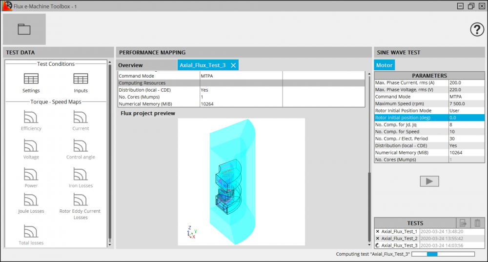
You can try the Flux tool FeMT (form Flux supervisor), to draw the curve torque VS speed. But you need to define the initial position and use also laminated region in the stator and rotor.
Best regards.
Thank you for your reply.
I apologies again as i am very new to this software and haven't been taught about it.
How would i impose a control angle, I have changed my Geometry parameter 'ANGLE' and in the Solving Scenario i have Controlled the parameter 'ANGLE' between 0 and 360 with a step value of 1, Also tried to control the Transient State by Rotor position from 360 to 1 with step value of 1 and another time controlled the transient state by 'Time'.
All these attempts haven't worked.
I also have tried to use FeMT but it dosn't seem compatible with Axial Flux Machines.
Apologies again
Here is the Report File.
Here is the Log File.
Hi,
Thanks for the file. When I saw the content of the log and report file there is no error message and solving of the project is done well. Except one error message about the iron losses computation. Did you change the region of the rotor and stator (use laminated region instead of non-magnetic conductrices region).
Can you share the FeMT file?
Best regards.
Here is the .FEMT file, with Axial_Flux_Text_5 & 6 which are the two runs which failed and im not sure why.


Hi,
There is an example in Flux supervisor about an axial flux motor. When you open Flux supervisor:
Select 3D
Open Example
Select application note >> Axial flux motor
Best regards.