How to creat 2D element from nodes
hi, everyone
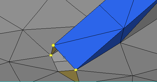
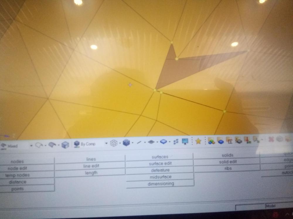
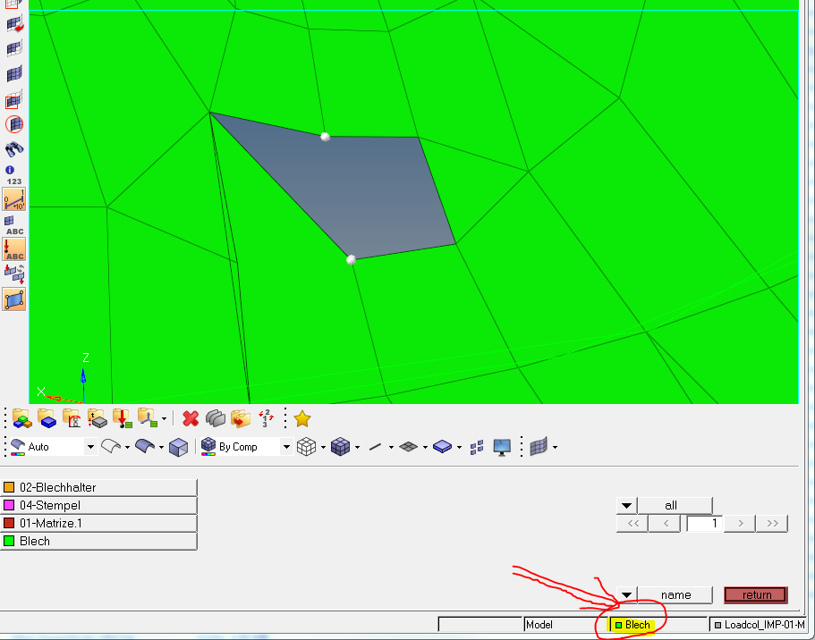
i'm a beginner in Hypermesh. Recently, i've encountered a problem in 2D meshing. I have 3 nodes (like in the photo below). I want to create a trias element from them, or creat some lines from them, so i go to Mesh - create - 2D element - Element. I chose those 3 nodes, but no element was created!!!
So could anyone tell me where i was wrong and how to fix this, thank you very much!!
Find more posts tagged with
Maybe your mesh is 'tria6' (2nd order), not 'tria3'. So in this case, you need define 6 nodes.
@Q.NGUYEN-DAI, i just run into the same problem, when i deleted 1 element and i want to creat a new element to patch, i could not create any element. when i choose the first 2 nodes, they are highlighted, but when i choose the 3rd nodes, all nodes are not highlighted anymore. so no element was created. I've attached my model below, could u take a look and help me know what exactly the problem is!! Thank you
Your mesh is 1st order, so for surface mesh, you need only 3 nodes for each element.
Attention 1: when you create element, have a look at CURRENT component, because new elements will be created on that.
Attention 2: Your current mesh is not so good. For TET4 meshing, you have to make finer mesh to get better results.
thank you @Q.NGUYEN-DAI, now i know where i was wrong /emoticons/default_biggrin.png' srcset='/emoticons/biggrin@2x.png 2x' title=':D' width='20' /> . I'll try to make my current mesh better. But you know, i am a beginner in Hypermesh, so could you give me some advices, some tools on that, i mean on making finer mesh, thank!
Even with 2nd order element, you have to make some elements on thickness. Only one element / thickness can not give you acceptable results.
Why not calculate with shell elements?
I agree, I would calculate with shell elements.
However, I have tested this myself. I created a simple model of a cantilever beam and compared different solid meshes with the max output von Mises stress result.
Via hand calculations (baseline): Stress = 600 MPa
1x HEX8 element through thickness: Stress = 565 MPa
2x HEX8 element through thickness: Stress = 604 MPa
1x TET4 element through thickness: Stress = 154 MPa
2x TET4 element through thickness: Stress = 387 MPa
1x TET10 element through thickness: Stress = 623 MPa
The results are a bit iffy because the max stress is located near the constraints (I should've done this using a 3-point bending model...) You can clearly see here that TET4 elements are bad at calculating stresses through the thickness due to bending. However the TET10 element (with midside nodes) is a lot better.
Still, for best results calculating stresses through the thickness I would be using HEX elements (where possible) for thick components and QUAD elements for thin shell components.
it will be great if you can send full screenshot... but for now I am assuming that your current component is different than where you are adding element. So please try with setting current component. For changing current component click on 'set current component' and choose appropriate(find attachment).
Hi,
F6>create
select 3 nodes and click middle mouse button (or click 'create')