Non adequation between 2D and 3D representation
Hi all,
I am working on an analytical problem of a circular plate under distributed loading conditions, and with all edge nodes constrained.
I first modelled the plate with 2D quad elements, thickness 0,35mm.
Then I modelled it with 3D brick elements, thickness 0,35mm (8 elements in the thickness).
Of course I would like to find the same order of magnitude concerning both results. But I do not in terms of deflection.
Does anyone has an answer to this ?
Thank you in advance,
Alice
Find more posts tagged with
Hi George,
I get 1mm deflection with shells, 7.10-2mm with Bricks.
The other parameter I check is the resultant force on the clamped edge, to be the sum of all nodes' loads. This is ok, but the deflection not...
2D plate:
- clamped nodes at edge
- all innner nodes under loading
3D plate:
- clamped nodes at edge on all layers (8 elements in thickness)
- all inner nodes on upper face under loading
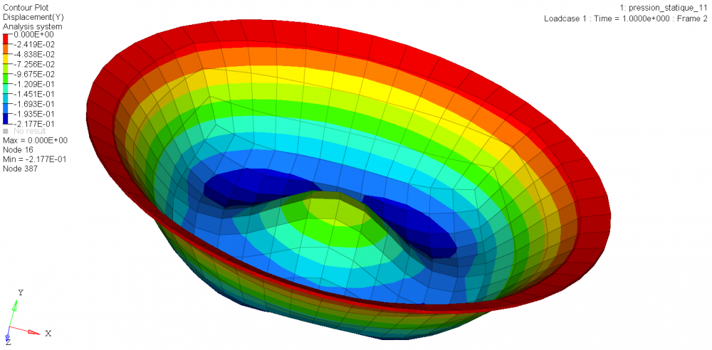
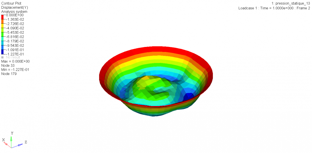
I try changing the properties /PROP/SOLID from Isolid = 17 to 14, as 14 is the default value for IMPLICIT option, I am using. I put Inpts to 222 and I get a deeper deflection but showing weird localisation (see attached picture, highly zoomed in to see the problem). It is as if I did not apply the load in the center, but I apply the same load as before, when I used Isolid = 17.
I read about the HA8 and H8C elements properties but do not understand how I can come to such wierd results on displacement. Could you explain me the differences between these 2 options ?
Thanks in advance


Hi Alice,
Normally it should give the same results. Only for the deflection you are getting a different result?.
Please see this link http://www.altairuniversity.com/wp-content/uploads/2014/02/meshing.pdf (Page No:5) where a similar case is done.