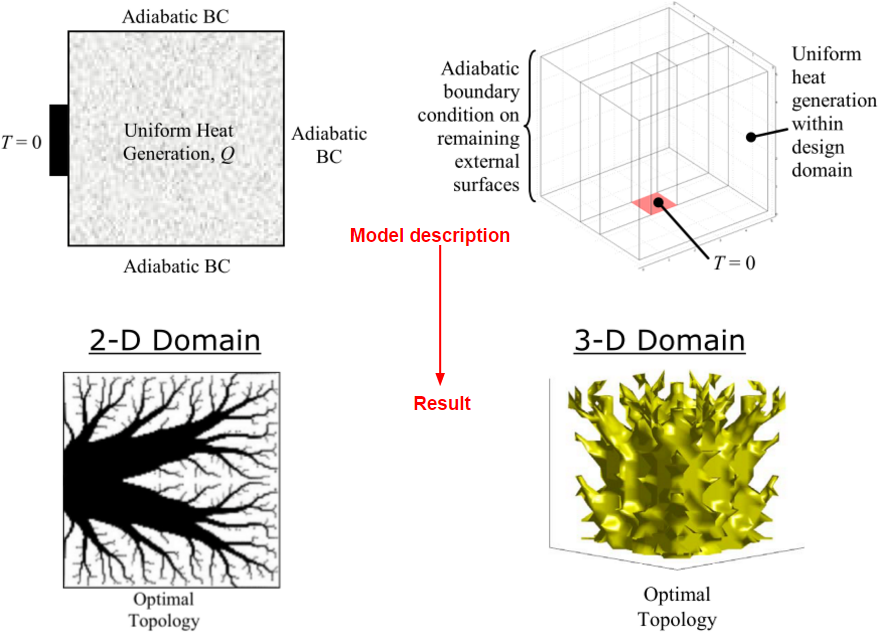
Classic thermal compliance optimization
Hi,
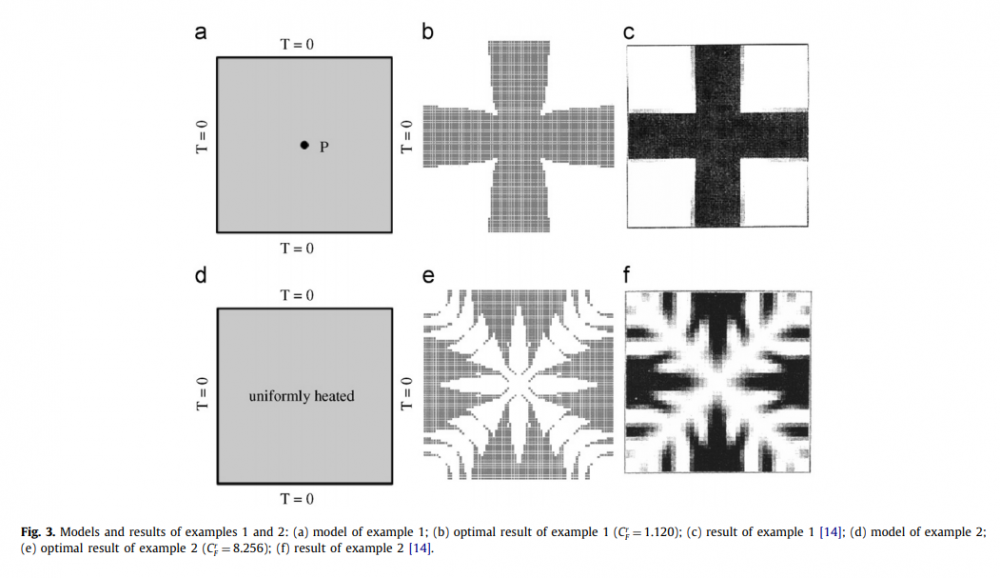
I am trying to do a simple optimization, refer to the following example.
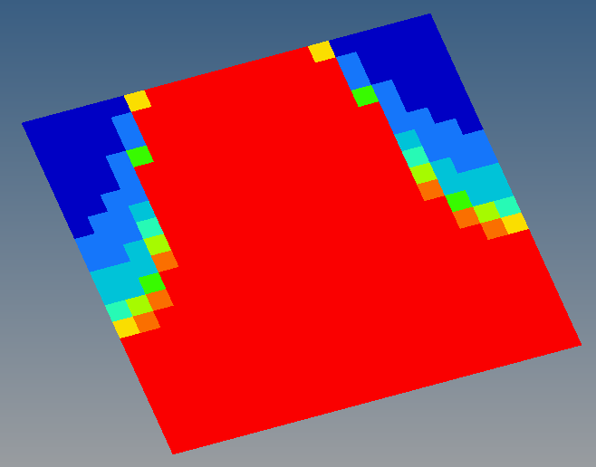
I have make a fixed temperature at the top middle edge, but have error to run.
How can I make a flux input to the entire surface? I am thinking that the flux input can't applied on Design_Space domain , right?
I also attached my FEM file, for your reference.
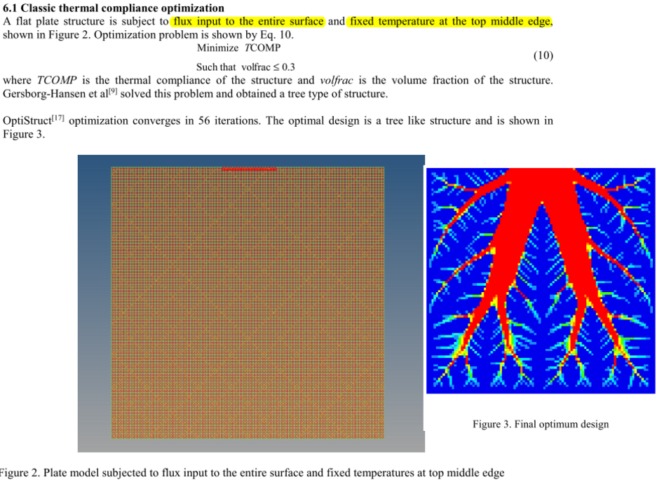
Find more posts tagged with
Hi Prakash,
Is there another method to set the Flux input to the entire plate (topology domain) ?
As refer to the example above, that comes from attached paper, the optimization can be done by using Optistruct.
Can I add heat flux to nodes/ elements without using CHBDYE ?
Hi Prakash,
Thanks.
Furthermore, is it possible to apply the heat flux on 3D solid elements (including outside surfaces and inside elements), so I can solve topology optimization in 3D domain.
Following photos are showing the 2D and 3D domain model descriptions and results.
Yes, you can have CHBDYE on solid elements. CHEXA, CPENTA, CPYRA and CTETRA are supported.
Hi Prakash,
Thanks.
I have change the heat flux type to QVOL, thus this type flux can be used to applied in design space domain.
Take the 2D problem as example, I got a different optimal result (following photo) compare to the tree like structure optimal.
Attached file is my model file.
Appreciate if you could help me to check my model and see how can I change the setting to get a tree like structure optimal result.
In the attached pdf, I see the analysis formulation is based on convection and conduction.
To have a fixed temperature you can constrain the nodes without any Dofs and edit the SPCs to provide temperature boundary condition.
It is a little difficult to such a structure just based on assumed values.
Hi Prakash,
Thanks.
I have change the heat flux type to QVOL, thus this type flux can be used to applied in design space domain.
Take the 2D problem as example, I got a different optimal result (following photo) compare to the tree like structure optimal.
Attached file is my model file.
Appreciate if you could help me to check my model and see how can I change the setting to get a tree like structure optimal result.
<?xml version="1.0" encoding="UTF-8"?>
![]()
How are you able to get that?
When I do the optimization process, all elements get removed.
What I did was add a 0 temp boundary condition on the middle nodes, and then added a QVOL flux over all elements. I then set the Obj function to min thermal compliance under a volume constraint of 30%. The entire mesh was set as design variables. But it still ends up trying to remove all elements.
Sure.
I've also checked wumindao's file. He set the temperature to 1 instead of 0. That gave me some results, but it still doesn't match with the one in the paper that wumindao linked in his first post. I also noticed when I zoomed into the pictures, that the elements seem to have a convection elements included, which isn't allowed for topology optmization.
Also, according to another paper https://www.sciencedirect.com/science/article/pii/S0168874X08000905 I should be able to optimize the structure with 0 temp boundary condition on the outer edge without convection included (like in the image below).
<?xml version="1.0" encoding="UTF-8"?>
So I ran a 100x100x100 3d model with an element size of 2mm and I had to manually add the surface elements one layer at a time just to ensure that I have conduction elements at least touching one face of the internal elements (So not all faces if an element has those elements attached). And I did get the results I was expecting as you can see below from the mid section view and full view.
But, this was a time consuming process. Is there an efficient way to do this?
If I was to only add the surface elements to the outside face, and add Qvol to the internal elements, I end up getting the shape shown below.
If I was only to add the surface elements on the outside faces (Without internal QVol), I get the shape below. And it doesn't match what I should be getting.
Thanks
Hi @Alucard
Can you get the same result as the paper for 2D case? (My first post) Like this. I have tried several times and still could not get this and then I gave up. After that I use Top3d and got a quite similar optimal tree-like geometry both for 2D and 3D cases. For your 100x100x100 model, maybe you can try Top3d and see which one run fast.
By the way, could you share your 100x100x100 model with me? my email is wumindao@gmail.com
Thanks.
reducing the number of nodes (coarse mesh), more memory may help?!!
My issue isn't about memory or computational time though. It's about manually having to add the conduction elements internally to get the result that I wanted. If I Was to select all elements, Hypermesh will only add the elements to the external faces of the mesh. So in the case of my 100x100x100, I had to mask every other column and then added the conduction elements. This allowed me to have at least one face in every element that is attached to a conduction element. If I didn't do this, I wouldn't get the results that I'm looking for. Is there another efficient way I can do this?
@wumindao
Yes, the file Prakash shared with me is able to obtain the same results. QBDY1 load has to be applied to the slave conduction elements. And two cards needs to be defined (OPTI_DEBUG and CASE_UNSUPPORTED_CARDS). I sent you both the 2d and 3d files.
I did try Top3d but Matlab ran out of memory when I tried to run a larger model.
@Alucard I too am working on a 3D model for this. Were you able to create conduction internally too without masking each row/column. Also do you have any alternate way of contacting you? Also, you are modelling conduction internally and not any convection conditions on the outer surface of the cubes right?
Thanking You,
Amogh Taraikar
So I ran a 100x100x100 3d model with an element size of 2mm and I had to manually add the surface elements one layer at a time just to ensure that I have conduction elements at least touching one face of the internal elements (So not all faces if an element has those elements attached). And I did get the results I was expecting as you can see below from the mid section view and full view.
<?xml version="1.0" encoding="UTF-8"?>
But, this was a time consuming process. Is there an efficient way to do this?If I was to only add the surface elements to the outside face, and add Qvol to the internal elements, I end up getting the shape shown below.
<?xml version="1.0" encoding="UTF-8"?>
If I was only to add the surface elements on the outside faces (Without internal QVol), I get the shape below. And it doesn't match what I should be getting.
<?xml version="1.0" encoding="UTF-8"?>
Thanks
Hey @Alucard @Prakash Pagadala
I am interested in the work you guys have done. Do you have any tutorial video or user guide to generate thermal topology of 3d objects? if not can you show me how you did it for this problem? My email address is aa.sutaria@gmail.com.
Thanks
Ankit Sutaria
Can you share 2D or/and 3D sample generate thermal topology ?
Thanks
Best regards
Andrey
Can you share 2D or/and 3D sample generate thermal topology ?
Thanks
Best regards
Andrea
Ankit1994
did you have any tutorial video or user guide to generate a thermal topology of 3d objects?
if yes, can you please share that with me?
My email is soudas46@gmail.com
You can find reply in below post.
https://community.altair.com/community?id=community_question&sys_id=8e66003a1b2bd0908017dc61ec4bcb81
Hello @Alucard ,
Can you please help me with the classic thermal compliance 2D case?
You told earlier, ' QBDY1 load has to be applied to the slave conduction elements. And two cards '
needs to be defined (OPTI_DEBUG and CASE_UNSUPPORTED_CARDS'
can you please let me know how to do that?
thanks in advance /emoticons/default_smile.png' srcset='/emoticons/smile@2x.png 2x' title=':)' width='20' />
So I ran a 100x100x100 3d model with an element size of 2mm and I had to manually add the surface elements one layer at a time just to ensure that I have conduction elements at least touching one face of the internal elements (So not all faces if an element has those elements attached). And I did get the results I was expecting as you can see below from the mid section view and full view.
<?xml version="1.0" encoding="UTF-8"?>
But, this was a time consuming process. Is there an efficient way to do this?If I was to only add the surface elements to the outside face, and add Qvol to the internal elements, I end up getting the shape shown below.
<?xml version="1.0" encoding="UTF-8"?>
If I was only to add the surface elements on the outside faces (Without internal QVol), I get the shape below. And it doesn't match what I should be getting.
<?xml version="1.0" encoding="UTF-8"?>
Thanks
Hey @Alucard @Prakash Pagadala
I am interested in the work you guys have done. Do you have any tutorial video or user guide to generate thermal topology of 3d objects? if not can you show me how you did it for this problem? My email address is aa.sutaria@gmail.com.
Thanks
Ankit Sutaria
Ankit, did you happen to receive the work of @Alucard ? I would really appreciate it if you could give me any leads regarding this.
@wumindao
You will end up with this message when you have CHBDYE on design space
CHBDYE can't be applied in topology or free-size design domain.