how to simulate a gear rolling forward and at the same time moving forward in motionview?
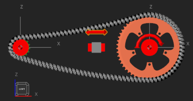
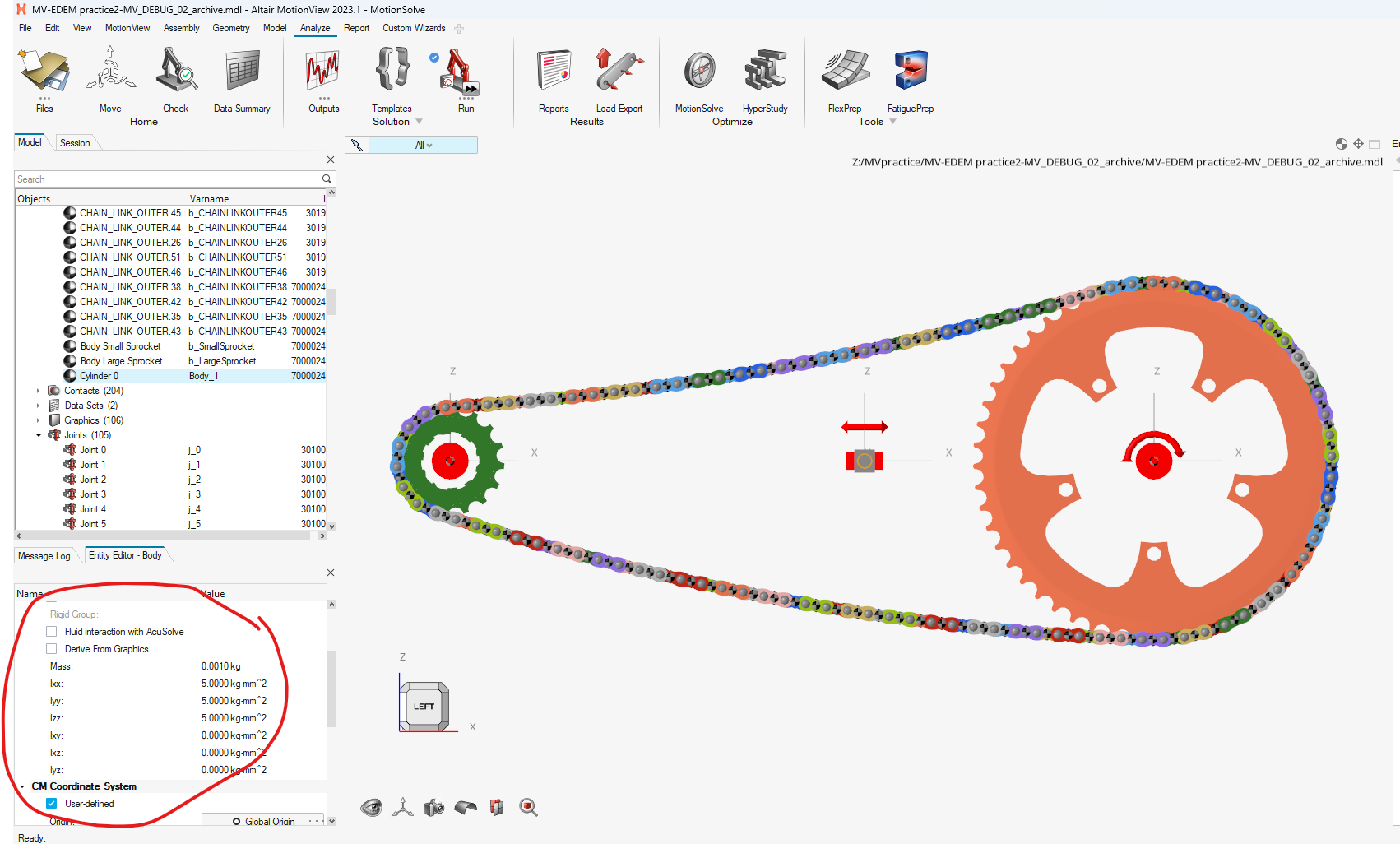
Description: i am a student, new to motionview, and i want to simulate a gear rolling forward and at the same time moving forward. But these two motions are independent, like the gear on the bike when bike is moving, the rolling and moving are not related, they have different velocity.
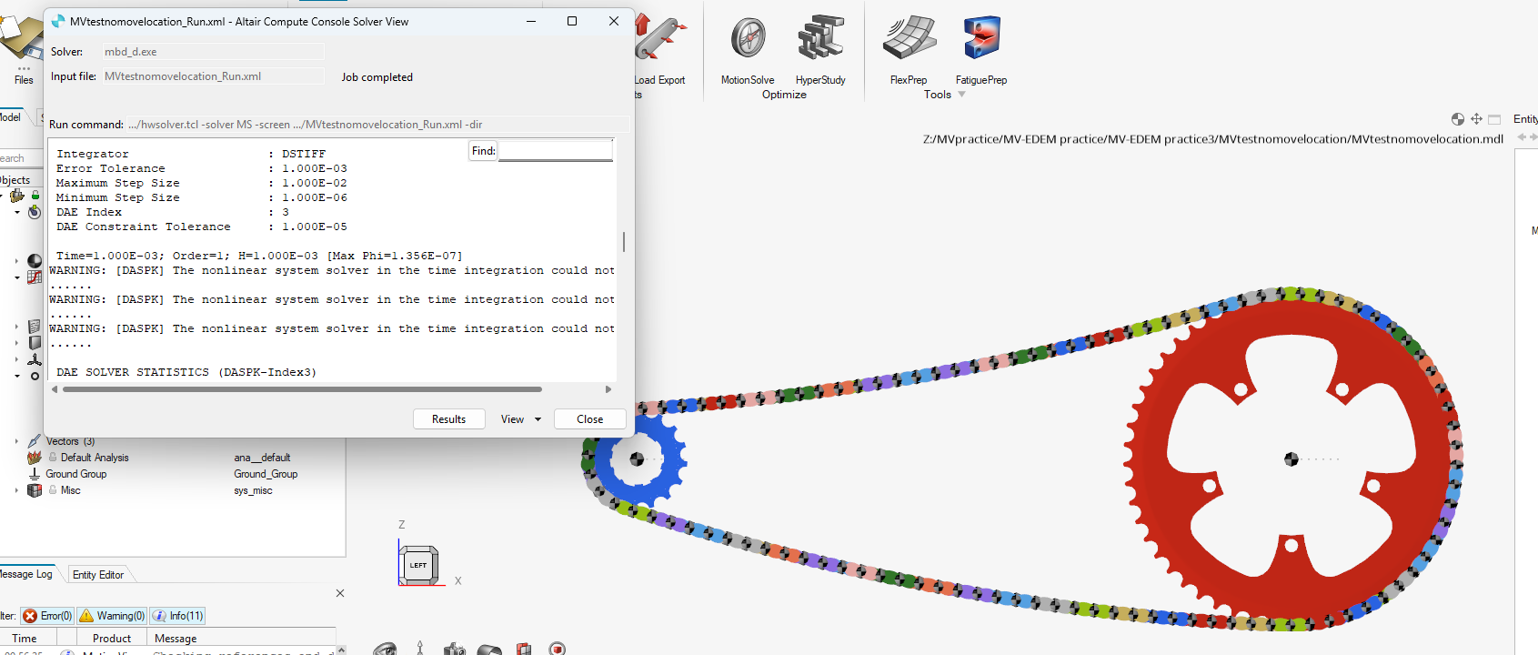
i tried to use a revolute joint and translational joint, but the log reports redundant constraints warning, and the animation is also incorrect.
therefore, i'm kindly asking for help, thank you.
Product/Topic Name : motionview2023.1
Find more posts tagged with
Hello Vishvam,
Thank you for demo model. My end goal is to simulate a motion just like the Chain and Sprocket, and the whole system is also moving forward with a constant speed. Then I want to do a co-simulation with EDEM to get the loads on the chains.
So you mean you would suggest me to use Altair Inspire instead of Motionview to simulate the motion?
Hello @KeyuWang_UWO,
Inspire motion is a CAD based MBD tool. Here is the elearning for the same if you'd like to explore more. The model from Inspire motion can be exported to the Motionview MDL file, for advanced modelling features. But if your end-goal is cosimulation with EDEM, then it'd be possible only with Motionview and not Inspire currently.
Hello Vishvam,
Thank you for the reply. so this is the model and motion i want to simulate:

Chain and Sprocket. Sprocket rotate about the y axis, causing the chains to rotate also. And the sprockets are meanwhile translating in the x axis with the same velocity.
Is it possible to do the simulation in Motionview without turning off gravity?
Hello @KeyuWang_UWO,
Please refer to the attached modified model. The PTCV joint is created at the center of the gear, so that it's more stable in addition with a planar joint, to allow translation and rotation in the plane. The model looks well, but the chain would still need to be complete, as it's constrained only with the help of contacts.
For additional dedicated support, I'd suggest you to create a support ticket by mailing to hwsupport@altair.com. The MBD subject-matter experts will be able to help.
Hello Vishvam,
Thank you for the help. Please bear with me for another question. In the PTCV joint model you sent me, the planar joint is deactivate and everything works fine. Then why do I need the planar joint activated in my model? The log is reporting redundant constraints with the planar joint when running and the animation is also glitching.
Thanks again, I will contact the the email for further questions.
Hello Vishvam,
This is Keyu again. I know we have solved this problem. And I have used it for several simulations. But suddenly something is wrong with the PTCV joint. When I only add the joints, there should not be errors. But it is showing non-linear system error. I don't know why.
Please take a look.
Thank you,
Keyu
Hello @KeyuWang_UWO,
The geometries seem to be missing in the attached model. Could you please reattach the model with CAD?
Regards,
Vishvam Naik
Hi @KeyuWang_UWO,
I would try to keep this simple and not overcomplicate the setup.
Just add an intermediate Body to facilitate this desired system motion. Connect from Ground to the intermediate Body with a translational Joint and from the intermediate Body to the sprockets each with revolute Joints. Put a Motion on the translational Joint and another on the large sprocket's revolute Joint. The speed or displacement of each Motion can be easily defined with a STEP function to slowly rotate and translate the system.
I had to use one of the earlier models you attached, as the most recent one did not have any contacts in it, but this motion application is identical to whichever chain and sprocket model you use.
Please see the example below:

Here, the rotation ramps up over 5 seconds and then the model translates over the last 5 seconds.
Hope this helps!
Adam Reid
Hello Adam,
Thank you for the reply. I can't add additional body to the geometry. This model is similar to a project I will work on. That's why I need your help to work this out. I have found out why the co-simulation is not showing correct motion—I have moved geometry location in EDEM, causing mismatch coordinates. Then when I try to redo the Motionview model to move its location. The PTCV joint is acting up. I have used it successfully before. So I'm not sure why. Could you please take a look. New attachment here.
Thanks,
Keyu
Hi @KeyuWang_UWO,
The cylinder graphic attached to the intermediate Body is purely for visual purposes. The Body is all that is required to achieve this simple topology. You can simply delete the cylinder graphic or exclude it from your selections when coupling to EDEM.

See below once again:

I strongly recommend not to use the Advanced Joints method.
Hope this helps!
Adam Reid
Hello Adam,
Thank you for the suggestion. After took a close look at your model, I understand your way now. It is a lot easier so I have decided to use your method.
My only question is that why do you need the intermediate body to have mass. Can I click the 'drive from graphic' to make it massless?

Also, since now the motions are defined on joints, when doing the co-simulation, can I move geometry location in EDEM?
Thanks again,
Keyu
Hi @KeyuWang_UWO,
The intermediate Body does not have a graphic attached, so if you select the Derive From Graphics option it may calculate to 0 kg but actually throw an error when you go to solve.
Regardless, it is not recommended to feature any Body that has zero mass, as it can cause instability issues for the solver. The mass shown of 0.001 kg is essentially massless.
Hope this helps!
Adam Reid
Hello Adam,
Regarding of this 'intermediate Body method', I have another question. Let's say I want the whole model to move down first(into the soil), then move forward. Right now the translational joint can only move forward. Do I just simply replace it with a planar joint?
Best,
Keyu
Hi @KeyuWang_UWO,
It looks like after you used the Move Tool, the distance between the sprockets changed. There is observable slack in the chain that is causing issues. Please ensure the distance between the sprockets is the same as before, or, apply what you have learned with the intermediate Body to a different model.
Secondly, you can add more intermediate Bodies as needed to add more translations or rotations the sprocket assembly. This is commonly referred to as "stacked joints" and is how you can apply translation in X, Y, and Z as well as pitch, yaw, and roll if needed.
Hope this helps!
Adam Reid
Hello Adam,
Thank you for the help, I have successfully run the Chain and Sprocket model.
Now I am doing the same to my project model. It is similar to the Chain and Sprocket model. But an error appears when I activate all the revolute joints on the chain. If I deactivate any one of them, the error is gone. This has never happened in the Chain and Sprocket model. Do you have any idea what the problem could be?
Best,
Keyu
Hello @KeyuWang_UWO,
The error is due to possible LOCKUP in the chain links. As the joints are rigid, the load coming on these revolute joints are too high. This issue was not seen in earlier model, as there was some slack in the chain. In your latest model, it's a very tight configuration. One way to resolve this is by making one of the joints as Compliant. So that you can allow some local deformation in the joint. But you'd need to re-look at the design and number of links in the model.
Attaching the model in which the deactivated joint is made compliant and this model runs well with the contact.
Hope this helps!
Hi @KeyuWang_UWO,
The cylinder graphic attached to the intermediate Body is purely for visual purposes. The Body is all that is required to achieve this simple topology. You can simply delete the cylinder graphic or exclude it from your selections when coupling to EDEM.

See below once again:

I strongly recommend not to use the Advanced Joints method.
Hope this helps!
Adam Reid
Hi @KeyuWang_UWO,
The intermediate Body does not have a graphic attached, so if you select the Derive From Graphics option it may calculate to 0 kg but actually throw an error when you go to solve.
Regardless, it is not recommended to feature any Body that has zero mass, as it can cause instability issues for the solver. The mass shown of 0.001 kg is essentially massless.
Hope this helps!
Adam Reid
Hello @KeyuWang_UWO,
2 Joints on a same pair of bodies cannot be created as this would lead one of the joints to be redundant due to over-constraint. In your case a Planar joint might be helpful which can allow the Translation in 1 plane, and also rotation along the normal of this plane. This gives you full planar freedom — like a puck on a table — which is ideal.
Then individual motions can be created at the markers to get the desired behavior.
Go through this link to know more about different types of Joints available in Motionview: JOINTS
Also if you are new to Motionview, then I'd suggest to go through the eLearning below:
MotionView/MotionSolve Introduction v2023
Hope this helps!
Hello Vishvam,
thank you for the reply. i have went through the eLearning course.
so according to your suggestion, i have set up a planar joint between the gear and ground. and defined the motions. but now it it reporting error in the model. i'm not sure why. let me tell you my setups:
the gear is positioned upright, so the translation is in the global x axis and rotation is along the y axis.
1.a planar joint at the gear center between the gear and ground, plane normal is pointing y axis.
2.a translation motion, marker1-gear CM, marker2-global frame, direction-translation along the x axis of marker2, property-velocity
3.a rotation, marker1-gear CM, marker2-global frame, direction-rotation about the y axis of marker2, property-velocity
4. a translation motion, marker1-gear CM, marker2-global frame, direction-translation along the z axis of marker2, property-displacement0
do you see any wrong in the steps? if so, please tell me how correct it.
thank you
Hello @KeyuWang_UWO,
Great that you have gone through the elearning. There is no one dedicated approach for modelling. In your case the error you might be seeing maybe due to the gear falling off due to gravity, as there is no other body/contact to hold the body in place. And it's free to move in the XZ plane due to gravity. So you can turn off the gravity and try that approach.
For single gear case, another great option can be using Advanced joints like Point-to-curve joint, wherein the gear follows a defined curve, straight line in your case, and the motion constraints would be the same as before. With the gravity activated here. I have attached both the models for your reference.
Hope this helps!
Hello Vishvam,
Thank you for the models. I can not turn off gravity because i also have chains contacting with the gear. Does this mean i can only use the point-to-curve joint?
Thanks,
Keyu