Problem with Cohesive Zone Modelling (CZM)
Hi everyone,
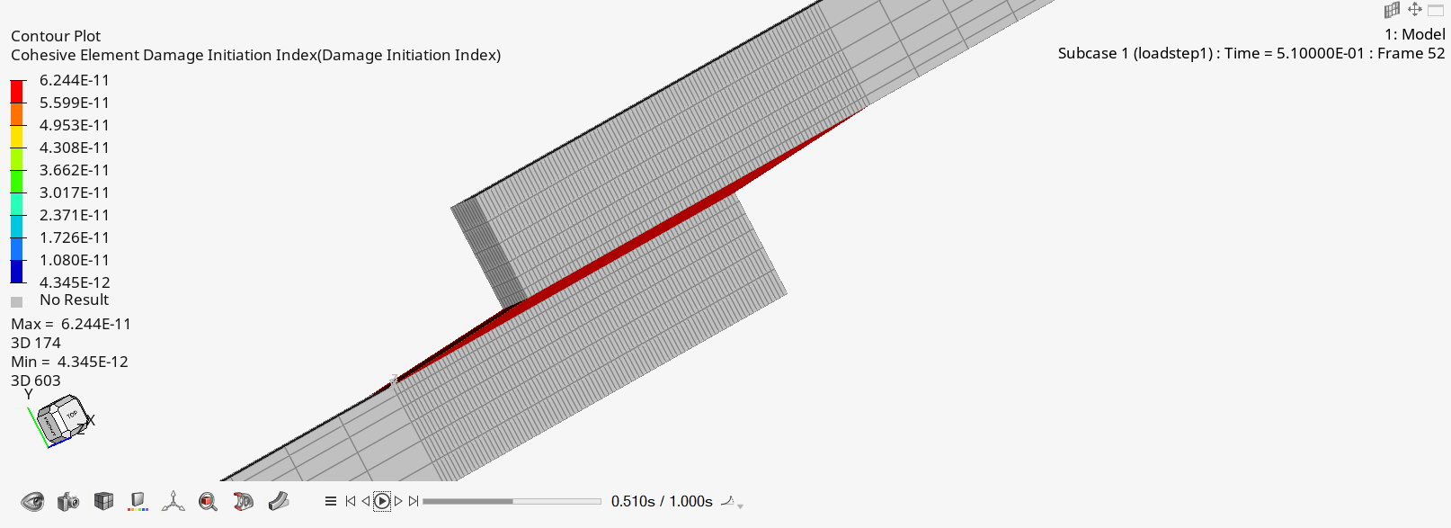
I'm using Optistruct to perform a Double Cantilever Beam adhesive debonding simulation and I'm getting illogical results. As you can see in the picture the adhesive is being stretched a lot and the bigger damage can be seen more towards the fixed end of the beam, which is not how it should be.
Could anybody help me on this? I'm attaching also the .fem model
Thank you so much.
Find more posts tagged with
Hi solon,
Thank you for your response, I'll try. I have also another question. The cohesive elements are stretching a lot even though I enter an high penalty stiffness (kn, ks, kt) which is not realistic. In addition they don't disappear when damaged. How can I fix this not logical behavior? In the picture you can see what is happening to my simulation in a single lap joint bonded with adhesive layer
Thank you again
Damage Index (Damage Evolution Index) is calculated for each cohesive element and it starts to grow above 0.0 when the damage for the element begins (that is, when the cohesive damage initiation index reaches 1.0).
Also, in the model you shared you are imposing large enforced displacement. In that cases large displacement analysis should be used. Please add PARAM,LGDISP,1 to your bulk data.
Bellow, you can find the model with the suggestions I made earlier: Large displacement. constrain Y,Z DOFS and enforce displacement on X direction. The elements are reaching damage index=1.0
According to the documentation: if at least one integration point of the cohesive element is in compression, then it will not get eroded.
Hi,
After some further reviewing of the model. Delamination opening direction I is defined from the grid sequence, and it is perpendicular to the bot/top surfaces.
You can re-order the nodal sequence in CIFHEX cards, so that the bottom and the top surface are as expected. You can use solid mapped mesh where the bottom surface mesh comes from existing temporary shell mesh.
Hello,
The cohesive material coordinate system is defined as the element local coordinate system by default or a prescribed system (CORDM = Integer ≥ 0). The material local 3-direction is taken as the cohesive normal direction corresponding to Mode I fracture, and the material local 1- and 2-directions correspond to Mode II and III fracture.
Please define a local coordinate system in PCOHE, CORDM field, to make sure that you are capturing the correct fracture mode.