🎉Community Raffle - Win $25

An exclusive raffle opportunity for active members like you! Complete your profile, answer questions and get your first accepted badge to enter the raffle.
Join and Win

How to map ADCRESULT input to actual pins on board.

User: "Altair Forum User"
Altair Employee
Updated by Altair Forum User

Submitted by BeachCat on Sun, 08/02/2015 - 22:55 

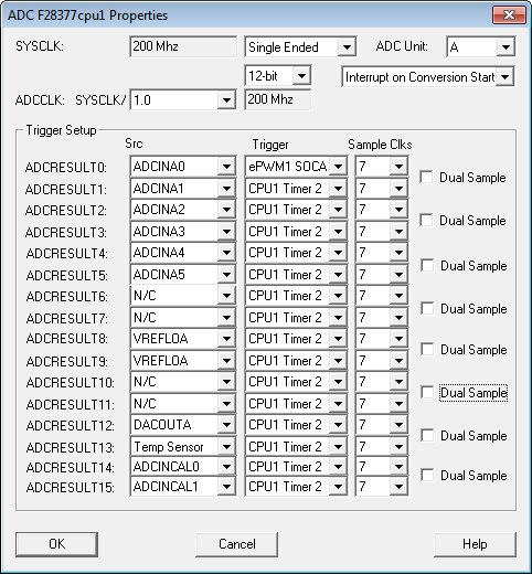
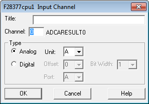
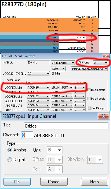
I have a F28377D experimenters board, how do I setup VisSim to read specific pins on the board with the ADC ?

I have the TI pinouts see attached file for the board. But cant see how to map VisSim ADC blocks to them.

‹ 'Target Open failed' trying to download 

Find more posts tagged with

Sort by:
1 - 6 of 61
    User: "Altair Forum User"
    Altair Employee
    OP
    Updated by Altair Forum User
    Submitted by pete on Tue, 08/04/2015 - 02:07.

    You do that via the ADC Config... screen. Note that their are 4 separate ADC units on the 28377, named A,B,C and D. So there are 4 separate sets of ADCxRESULTn regs. In the upper right corner of the ADC Config screen you choose the ADC unit.

    • The first column lists the result registers for a given unit.
    • The 2nd Src column lets you set the external ADC pin that will be sensed. (N/C mean No Connection)
    • The 3rd Trigger column selects the trigger to start an ADC conversion on that channel.
    • The 4th Sample Clks column lets you choose the clock duration of the ADC sample window. Hi impedence signals require longer sampling intervals to produce an accurate value.

    ADCF28377-config.png

    To read a result register into the diagram, select an Embedded > Delfino > Digital/Analog input. To configure it to a particular ADCxRESULTn register, right click the block and select the ADC unit and channel.
    F28377-ADC-chan-config.png

    User: "Altair Forum User"
    Altair Employee
    OP
    Updated by Altair Forum User

    Submitted by BeachCat on Tue, 08/04/2015 - 03:52.

    Yep, tried that here are the settings I used along with the vsm file, everything seems to be set as should be.


    F28377Dsettings.jpg

    Unable to find an attachment - read this blog

    User: "Altair Forum User"
    Altair Employee
    OP
    Updated by Altair Forum User

    Submitted by pete on Tue, 08/04/2015 - 04:06.

    You have ADCBRESULT0 set up to trigger on ePWM1 SOCA. Do you have ePWM1 set up to send SOCA on a proper event?
    If not, it's described here

    User: "Altair Forum User"
    Altair Employee
    OP
    Updated by Altair Forum User

    Submitted by BeachCat on Tue, 08/04/2015 - 05:04.

    Yes I checked that.

    I even found there is a signal on channel 3 & 5 of all the ADC units and my VisSim diagram plotted it ok.

    I also found that if I disconnected the DAC that was using the default ADC A 0 pin, it still would not work.

    User: "Altair Forum User"
    Altair Employee
    OP
    Updated by Altair Forum User

    Submitted by pete on Tue, 08/04/2015 - 05:18.

    Attach your .vsm file to your post so we can give it a try.

    User: "Altair Forum User"
    Altair Employee
    OP
    Updated by Altair Forum User

    Submitted by BeachCat on Tue, 08/04/2015 - 05:23.

    It's attached to my second post.