A program to recognize and reward our most engaged community members
Hi Folks,
Is there an example I can find for applying a base motion in the form of displacement to translationally constrained DOF's on a node using the SPC/SPCD card?
Thanks
I assumed that bottom of the honeycomb is clamped I'm not sure if this is true or not.
how to model this
it it is clamped, just add a SPC to it.
yes I have some results for this test
I can only share results private message
If you want to see I will send
for clamping you should just use SPCs at the base of your honeycomb.
For all the connections between honeycomb and Jigs you could use TIE/FREEZE contact to bound parts together, and reduce computational cost, as you wouldn't need so finer mesh for the Jig.
Dynamic problems, are affeted by mass and stiffness. If your masses are ok, then probably your stiffness and connections are not so good, or material properties are not correct.
You need to compare first expected frequencies against numeric ones.
That's all I can say to you. Maybe others can help you better.
it is ok, I did what you said
masses are ok, material tensile simuation were performed and compared tensile results are agreet to each other however when I use contact I could obtain close resuls and model with rbe elements is closer.
Unable to find an attachment - read this blog
@Adriano A. Koga
I should take into account thickness both rigid plate and honeycomb, should not I?
yes. Thickness needs to be there so that mass is also considered.
While for contacts, usually you can define the Search Distance to guarantee that your contact is fully working. But the defaults usually work as well as they take into account your master plate thickness.
ok, I will share a new model
@Adriano A. Koga I cannot define contact pls help
As you already have a rigid body in the lower plate, there's no need to use a material with so high Young's modulus.
This could take to numerical singularities.
Your constraints look strange to me, as your model is only constrained in X direction in the upper plate.
As you use EIGRL V1 - 1.0, you will not see any rigid body modes, but they're there, meaning your model is not constrained.
I've changed a little bit your contact definition and some material properties.
But you should investigate further your boundary conditions. They should reflect what you have in your test. I assume the lower plate is the concrete base, and if so, it should be grounded. (create a SPC at the reference node of the rigid body)
<?xml version="1.0" encoding="UTF-8"?>
thank you for all your all support but these numerical results no agreed to my experiments
I obtained lower modal frequencies from the experiments
10% maximum difference for lower modes?
it is not good, but not so bad, i would say.
Your FEA model shows stiffer behavior, with frequencies consistently above the experimental results.
If mass is correct, then, stiffness might be a little off.
Sometimes material data is not 100%, or mabe the contact has induced a little more stiffness than desired.
Another point, did you perform a mesh sensitivity analysis? probably refining your mesh would make it more flexible, thus frequencies would be closer.
I compared tensile simulation and tests and good agreed no problem.
the model you shared, is too different and never agreed with experimental results I would like to say that contact increase stiffness of the model
I'm doing with rbe what you're doing with your contact algorithm I have shared experimental results and numerical results for you at ppt
Whatever, thank you for all support
I want to ask another question;
in frf analysis, Can we see the behavior of the structure, for example displacement, at any frequency as a contour plot or how do we do it?
I don't get it. The model you shared is different from the PPT?? i'm confused here.
your last model seems to miss the proper boundary conditions. You are running a normal modes but have not constrained the base. This is already a big issue, in my point of view, as you can see in the GIF i've sent before.
I've only sent you a base contact configuration so that you adjust your BCs, specially a the base.
Concerning FRF, yes, you will be able to evaluate displacements over your entire frequnecy range (requested), just like the graphs that you've sent in the PPT.
There are a few tutorials in OS Help that shows the process.
actually, i've noticed that i was looking it upside down.
Anyway, your upper plate has what total mass?
I see a mass of 0.74Kg in your rigid body + the plate mass. What should it be?
I think a mistake was happened everyting was mixed I'm sorry,
there are so many model files that they are all mixed up
don't get it. The model you shared is different from the PPT?? i'm confused here.
I the file I mentioned is attached its results are closer to experimental results
see a mass of 0.74Kg in your rigid body + the plate mass. What should it be?
I shared above but rigid mass dont 0.74 but 0.745
how to do it? which tutorials
lunch help, go to OptiStruct section, then you will find OptiStruct tutorials, and you will find them under Advanced Small Displacement Finite Element Analysis
did you looked at the results
I've changed your solid model to shell with contacts. Results are similar.
Subcase Mode Frequency Eigenvalue Stiffness Mass 1 1 3.965253E+01 6.207284E+04 6.207284E+04 1.000000E+00 1 2 4.720448E+01 8.796828E+04 8.796828E+04 1.000000E+00 1 3 6.231411E+01 1.532966E+05 1.532966E+05 1.000000E+00 1 4 6.477586E+01 1.656480E+05 1.656480E+05 1.000000E+00 1 5 1.310828E+02 6.783461E+05 6.783461E+05 1.000000E+00 1 6 1.429535E+02 8.067697E+05 8.067697E+05 1.000000E+00 1 7 1.267066E+03 6.338083E+07 6.338083E+07 1.000000E+00 1 8 1.433586E+03 8.113483E+07 8.113483E+07 1.000000E+00
thank you for all my friend
/profile/97129-adriano-a-koga/?do=hovercard' data-mentionid='97129' href='<___base_url___>/profile/97129-adriano-a-koga/' rel=''>@Adriano A. Koga
you have done what you suggested contact instead of utilizing of rbe greetings (Much obliged!) but I modelled rigid mass as four solid elements (CHEXA) numerical results agreed with experimental results. I want to conduct an optimization study to optimize the thickness of the specimen when a contact algorithm was installed between rigid mass and the specimen, and I leave a gap by 0.5 mm ( this value is half of the specimen thickness). My problem begins here. Since I purpose to optimize the thickness, I want to define the gap value as a function of the thickness (for example, t/2) how to solve this problem
best regards and thank you for replies
hi /profile/32816-durukanbdilek/?do=hovercard' data-mentionid='32816' href='<___base_url___>/profile/32816-durukanbdilek/' rel=''>@durukanbdilek
The t/2 correction is mostly valid for full NL contact analysis.
In your case, if I recall correctly, you're using FREEZE/TIE contact, so this small difference won't be so important in your model.
For optimization use the gauge optimization, and take care on defining well your optimization problem so that you get what you expect. (just like any other analysis, in optiization if you don't define it correctly, garbage results will be generated).
The t/2 correction is mostly valid for full NL contact analysis. In your case, if I recall correctly, you're using FREEZE/TIE contact, so this small difference won't be so important in your model.
no problem in this part, numerical and experimental results were agreed with each other.
Look, I want to realize an optimization study and I want to use thickness (t) as a design variable do you understand me
I would like to define the gap, between mass and specimen as a function of the specimen thickness (gap=t/2).
how to define this parameter and this function or has hypermesh such as possibility ?
But your specimen is tied to your piece? If it is tied, like I said, the difference is expected to be low.
Anyway, of you want to be 100% accurate, yes, you can combine both things.
You will have 2 design variables:
- size/gauge desvar for T
- shape desvar translating your specimen (let's say unit translation in thickness direction)
Coupling of the 2 desvars can be acomplished by desvar link (dlink).
You can link the 2 desvars by a simple linear expression, by using translation_shape = 0+ 0.5*thick_desvar
yes, I made tie contact. experimental and numerical results agreed
I got what I want..
the problem is optimization I have only one variable is thickness of specimen because I want to define the gap as a function as thickness
I have a model file but its size is very large how to send to you
I will say again..if you're using tie contact, the gap shouldn't be that important in your analysis.
If you really want to go further with this, i've already described what you need to do:
But your specimen is tied to your piece? If it is tied, like I said, the difference is expected to be low. Anyway, of you want to be 100% accurate, yes, you can combine both things. You will have 2 design variables: - size/gauge desvar for T - shape desvar translating your specimen (let's say unit translation in thickness direction) Coupling of the 2 desvars can be acomplished by desvar link (dlink). You can link the 2 desvars by a simple linear expression, by using translation_shape = 0+ 0.5*thick_desvar
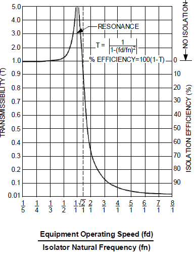
I intent to optimize the thickness (t) for transmissibilty(a(out)/ain) where a is acceleration or displacement.
You can create your desvars as described before, and for responses tou can create 'frf acceleration'.
Just take care when using a frf responses as you need to think well if this would be an objective or design constraint.
As you will have a vector (amp x freq) you need to correctly define this, if you want a specific frequency, or a maximum value, etc..
that is ok. I need conduct the FRF analysis. I agreed.
as objective function, I want to optimizie the transmissibility curve which can be obtained from frf analysis of the model
a curve can be obtained as figure
In the analysis, I run a range of 10-100 Hz. For example, I aim to access 0.1 at 90 Hz by altering of t (thickness) or other parameters (in necessary)
Is this possible?
also I want to sent to you my model file, whose size is 90 Mb how to sent it
You could calculate your transmissibility by using advanced dresp2 or dresp3 with Compose.
Dresp2 allows you to create an equation and use this as objective or constraints.
Take a look at OptiStruct help for more details.
As for the model you can zip the fem file. It would get smaller.
But i don't have access to my computer now. Sorry.