Hello everyone,
currently I have some issues with modeling a flexible shaft.
I've imported a fem model of my shaft in MotionView via FlexPrep. During simulation the model definitely can bend, but it seems to have an infinite torsional stiffness.
These are the material specifications I made. I chose a very soft material, so that there should definitely be some kind of torsion. The property-card just refers to the material 'Gummi' and defines the shaft as 'PSOLID'.
<?xml version="1.0" encoding="UTF-8"?>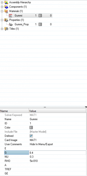
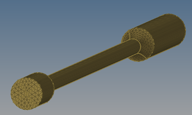
This is the shaft I want to use as a flexible shaft in MotionView:
This is the MotionView model I've created with the flexible shaft. To import the shaft as a flexible body I've used the Flexprep-Tool.
The two masses (about 20kg and 40kg) are rigid bodies and connected to the shaft with fixed joints.
The shaft is mounted on two revolute joints, each at the center of one side of the shaft.
The input is a sinusoidal rotational force at the center of the green mass and I measure the rotational displacement about the x-axis at the front and rear end of the shaft.
I expect a phase shift between the measured angle at the input and at the output due to the elastic properties of the shaft.

These are the visualised results of simulation:
<?xml version="1.0" encoding="UTF-8"?>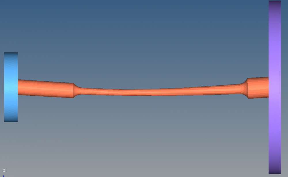
The shaft is definitely flexible and there also seems to be a torsion, but when I visualise the results in HyperGraph 2D, I get the following results:
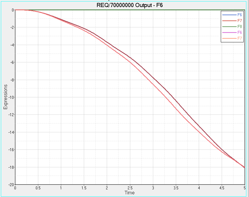
The upper curve is the result of the measurement at the front and rear end of the flexible shaft. It's exactly the same curve. F8 is the difference in the angular displacement at the forn and rear end, which is exactly zero.
The lower curve is the result of a reference measurement with a rigid shaft. Angular displacement at the front and at the rear end are - as expected - exactly the same.
Are there any additional solver options I have to activate or special things I have to consider while modelling the shaft to be able to measure a phase shift in the rotational displacement?
I urgently need some good advice!
Thank you in advance!
Your sincerely
