Collision Detection
Hi,
I used collision detection tool to find the intersection and penetration on the model.
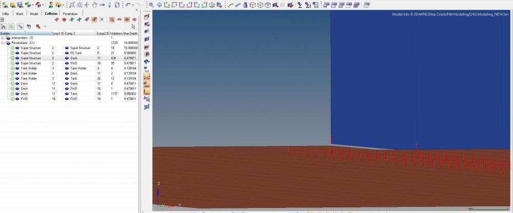
In my model there is a gap of 5mm between two components, but in collision detection tool its showing as a penetration as indicated by vectors.(as in below image)<?xml version="1.0" encoding="UTF-8"?>
Secondly, within the same component its showing as penetration as indicated by vector arrows. (Image attached below)
<?xml version="1.0" encoding="UTF-8"?>
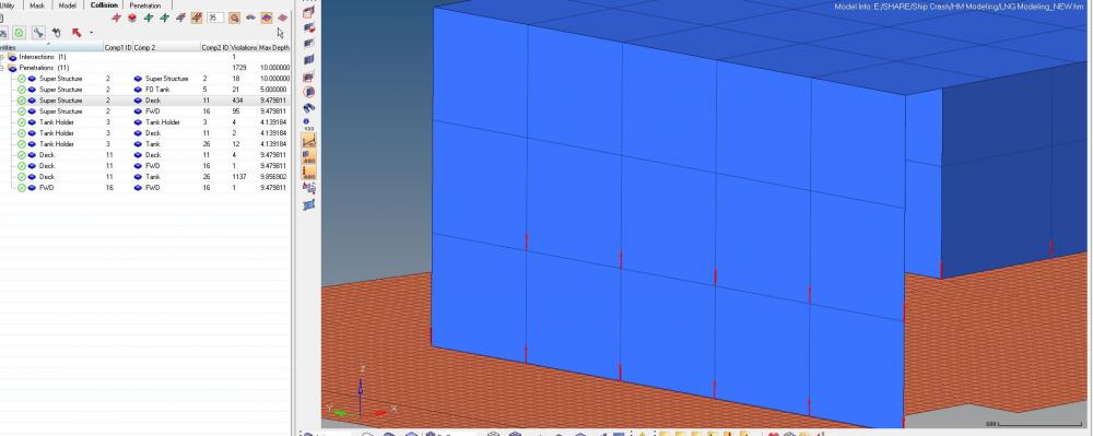
But when checking with the simple intersection tool (Analysis>safety>intersection) these are not shown.
How to resolve these.
Thanking You.
Answers
-
Hi,
Penetration is the overlap of the material thickness of shell elements. You can check the thickness of components.
The penetration depth also seems more in this case.
0 -
-
Hi,
In the second case are you considering any self interface?.
0 -
Hi,
There is no interfaces present now in the model
0 -
Hi,
Please share the model file through the secure dropbox.
0 -
HI George,
Shared the file.
0 -
Hi Pritam,
Please check your mail as I have shared you my observations.
0 -
Hi George,
Sorry to say that I have not received the mail.
Please resend or use this mail id: pritam.patel11@gmail.com
Thanking You.
0 -
Hi George,
I have seen your mail.
As I noticed you have not given any thickness, as there is no thickness assigned to any components till now.
If uniform thickness(say 10mm) assigned then there are penetrations. Can we ignore the thickness penetration between 2 components??
And regarding the contact, there is a fixed connection between all three components. I don't think TYPE 11 will provide a fixed contact as TYPE2
Thanking You.
0 -
Hi,
It's always recommended to clear all the penetrations in the model, else it may result in wierd model behavior which could result in run termination due to time step drop.
If you have a kinematic condition between components you can define Type 2 interface between those components.
0