Hello everyone,
I have some questions related to forming simulation which need your consultation.
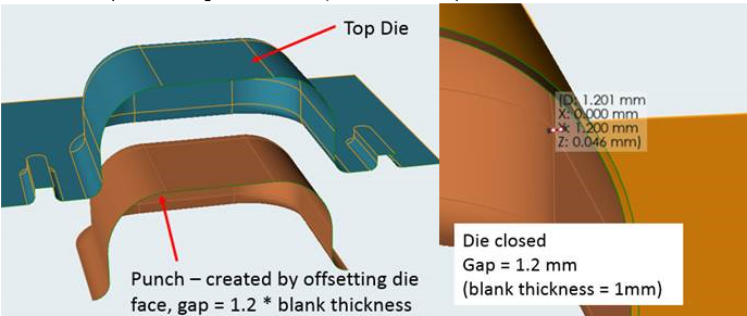
1. The 1st question is about the “offset value” when creating the tools.
a. By default, the offset factor when creating the tool is 1.2 (gap =1.2*blank thickness)
This value is also applied for the die closing gap.
It’s OK when we have only 1 part of the die set.
Take an example for a single action draw, we have the top die face >> use offset tool to create the punch and binder face >> run simulation.
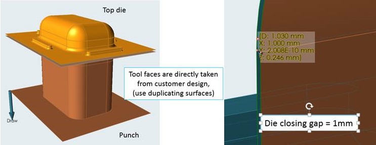
b. However, sometimes, we are provided with a full set of die tools, including the top die, punch, and binder.
And in the design, the gap is only equal to the blank thickness, for example = 1mm.
So what should we do in this case?
i. Take their design faces to use as tools, with the gap between die and punch = 1mm
ii. Recreate the punch by offsetting the die face >> gap = 1.2 mm (as above)
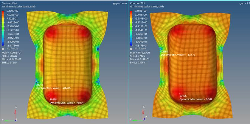
c. I have run a comparison for 2 cases above, the results are slightly different b/w 2 cases.
Other parameters are set the same (mesh size, binder force, friction…)
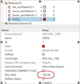
2. The 2nd question is about the material density in HyperForm and InspireForm.
Take an example for steel, rho = 7.8e-9 (ton/mm3)
If I use the uniform mesh size (turn off adaptive mesh), the density is remained originally = 7.8e-9 t/mm3
However, when using both InspireForm or HyperForm with the “adaptive mesh = on”,
The rho is increase 10 times >> new rho = 7.8e-8 (t/mm3) – check the model browser in HF
So may I ask about the purpose of this? Is it used to increase the time step >> reduce solution time?
And does it affect the result?
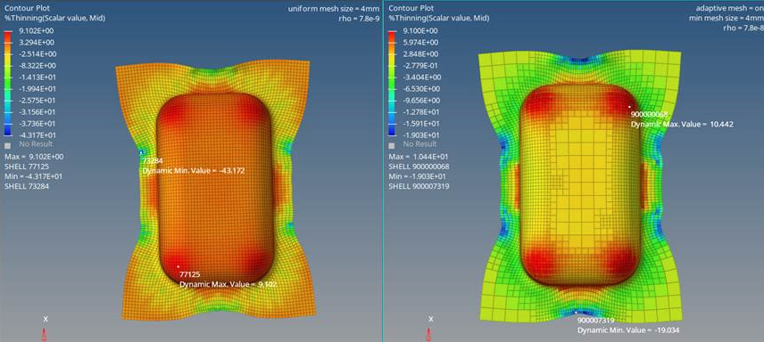
Since I have also made a comparison b/w 2 cases:
a. Uniform mesh size = 4mm (rho = 7.8 e-9)
b. Min adaptive mesh size = 4mm (rho = 7.8e-8)
The result are also slightly different.
Thank in advance!