Problem with constraints
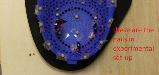
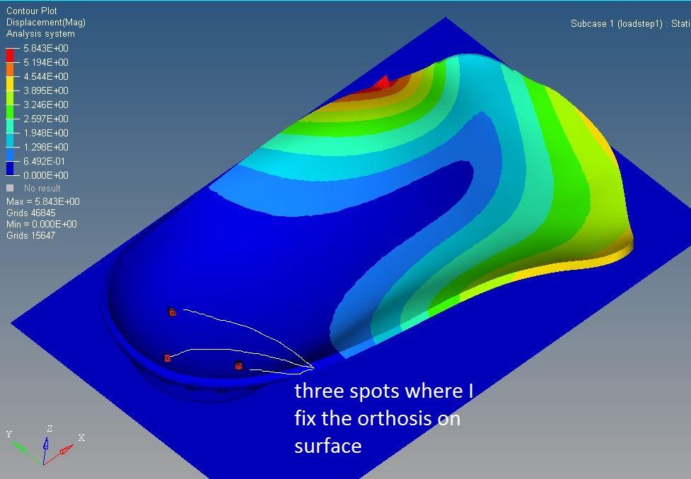
I am recently using Optistruct to validate the displacements of FE model with the experimental results. I have a foot orthosis in my set-up which has some holes in the back. I fix three holes with three nails on the back (as in the figure), and I apply load to foot orthosis. I control the value of loading with load cell to apply the exact value of loading in FE model, and also the loacation oif l;oading with tracking markers. To model the nail constraint, I fix three nodes instead of modelling a the nail fixation. However, when I fix all degrees of freedom, my displacement is much less than experimental model (half of real displacement). I also try to just fix the displacement not rotation, but my model rotates a lot. Can somebody tell me what is the best approach to model such constraint to be more realistic?
Thanks,
Maryam
<?xml version="1.0" encoding="UTF-8"?>
Answers
-
We need some information to comment:
Did you perform static analysis or nonlinear static analysis?
What are the sources of nonlinearity you have in your model(contact/material/geometric)?
How you model component 2d or 3d mesh?
0 -
Thanks for your response.
We did 'nonlinear quasi-static' analysis, and the source of nonlinearity we considered as non-linear contact properties.
Our components were modeled and meshed as 3D.
I also would like to add another question:
Our loading in experimental measures starts from zero, and then we increase it gradually until it reaches the maximum, then we reduce it to zero. However, in the model, we just applied the force as a force. We tried to add a TABLED1 with 3 points to progressively increase the force until its maximum value and to maintain tis value for a certain amount of time. However, we do not know whether we should keep it in force or we should change it to SPC? It will be great if you provide an example for applying gradual loading.
Thanks
Maryam
0 -
You can use CNTNLSUB for your requirement. This can be activated under subcase section or global case control.Please refer OptiStruct online help for more details.
The CNTNLSUB command can be used in the Subcase Information section to continue a nonlinear solution from a preceding nonlinear subcase, and thus create complex loading sequences.
0 -
Great thanks for your suggestion.
I still have problems with constraints. What would be the best way to simulate the constraints imposed by the presence of nails? Should I constrain all DOFs?
Thanks
Maryam
0 -
Hi Maryam,
from the plan view photo, it is unclear if nails fully constrain the Z DOF (coming out of the page). If foot orthosis can slide up and down along the nails then some kind of spring should have one end fixed in all DOF and the other end connected to the specimen, allowing appropriate compliance in Z direction and possibly even small rotations.
0