Hello everyone,
Currently, I am conducting a tensile and compression test simulation on a simple model. The model consists of two metal plates joined together by rivets (I modeled it simply using a rigid element), one end is fixed with 6 degrees of freedom, and the other end has a force applied along the axial direction (specifically the Y-axis) as shown in the figure.

Unfortunately, the simulation results were not what I expected. The model showed displacement along the Z-axis, meaning it was bending downwards instead of pulling along the Y-axis.

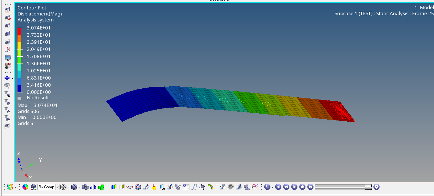
Even then, I fixed all directions except the Y-direction at the point where the force was applied.

The result was even stranger, as it was still bent along the Z-axis.


I can't figure out why this is happening. I would appreciate it if someone could explain and suggest solutions.
And I've attached two .fem files of the model here.
Thank you so much.
