Hello,
I am working on modeling a simple planar dipole antenna in Altair FEKO using two different feeding approaches. My goal is to simplify the feed model for use in array simulations with an infinite ground plane, while ensuring that the results remain consistent with a more physically detailed coaxial feed model and that the fabricated prototype matches the simulation.
Model Descriptions
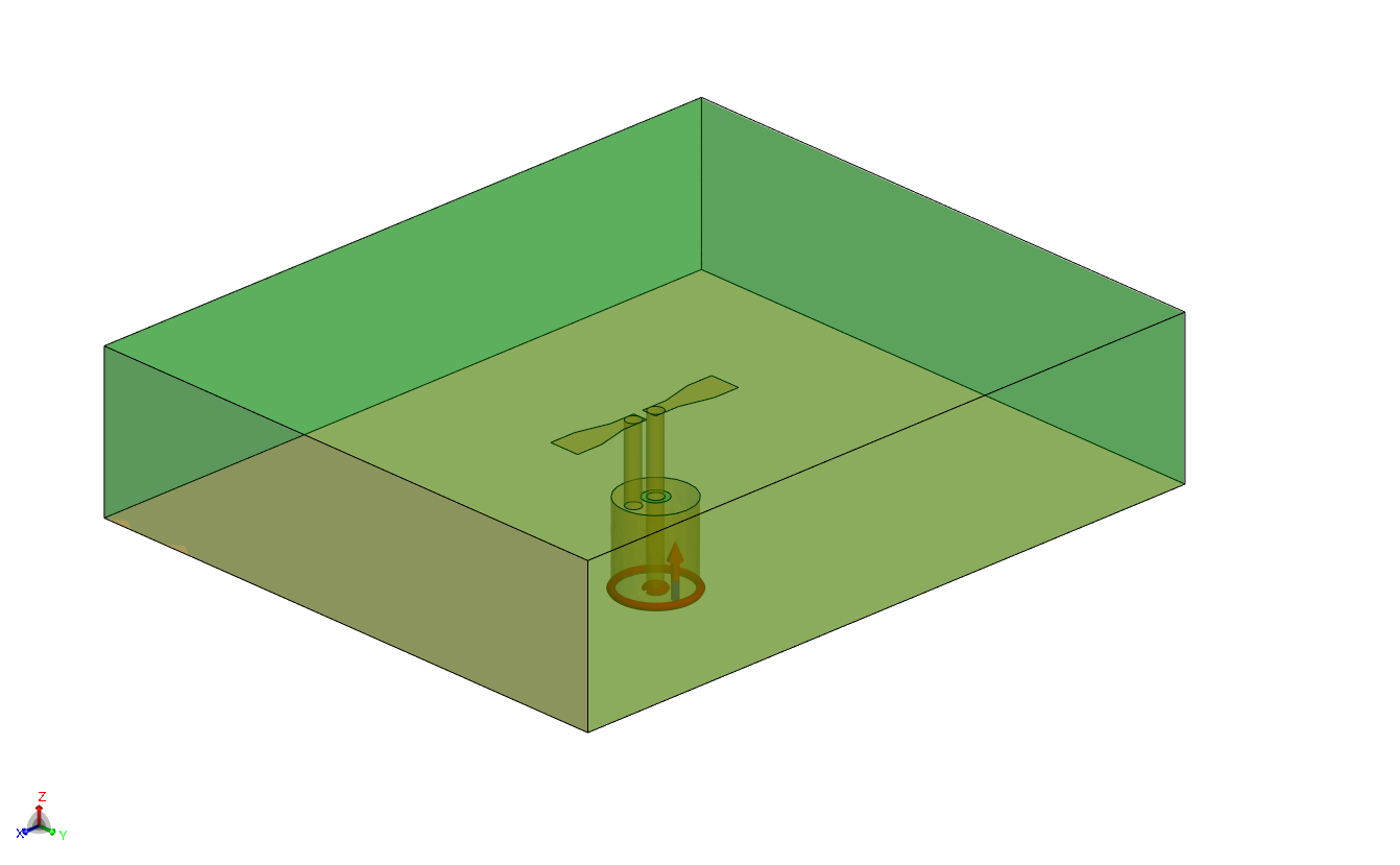
Model 1 – Coax Feed with Circular Waveguide Section
- The dipole is mounted above a finite ground plane.
- The feed is modeled using a circular waveguide port representing the coaxial connector.
- The length of the circular waveguide (after the ground plane) acts as an impedance transformer to match the dipole’s input impedance (which is higher than 50 Ω at the ground plane) to the 50 Ω coax source.
- The outer conductor of the waveguide connects to the ground plane, and the inner conductor excites the dipole arm.
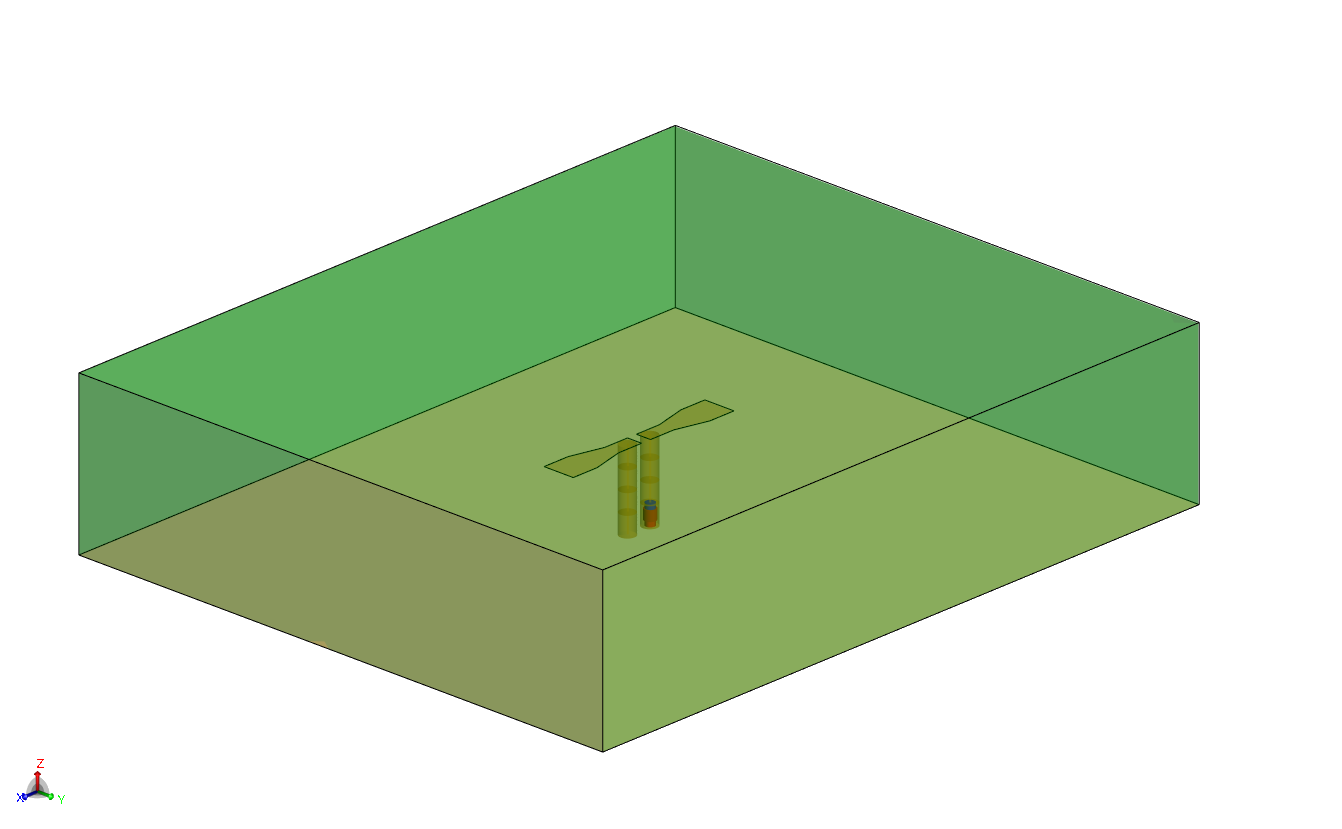
Model 2 – Simplified Line Feed
- A line feed excitation (voltage source) is used at the intersection of the feed line and ground plane.
- The same dipole geometry and substrate are used, but without modeling the coax or circular waveguide.
- The feed is directly placed at the dipole feed point, maintaining the same distance between the dipole and the ground plane.
- This model is intended to be used later with an infinite ground plane for array simulations to reduce computation time.
Issue
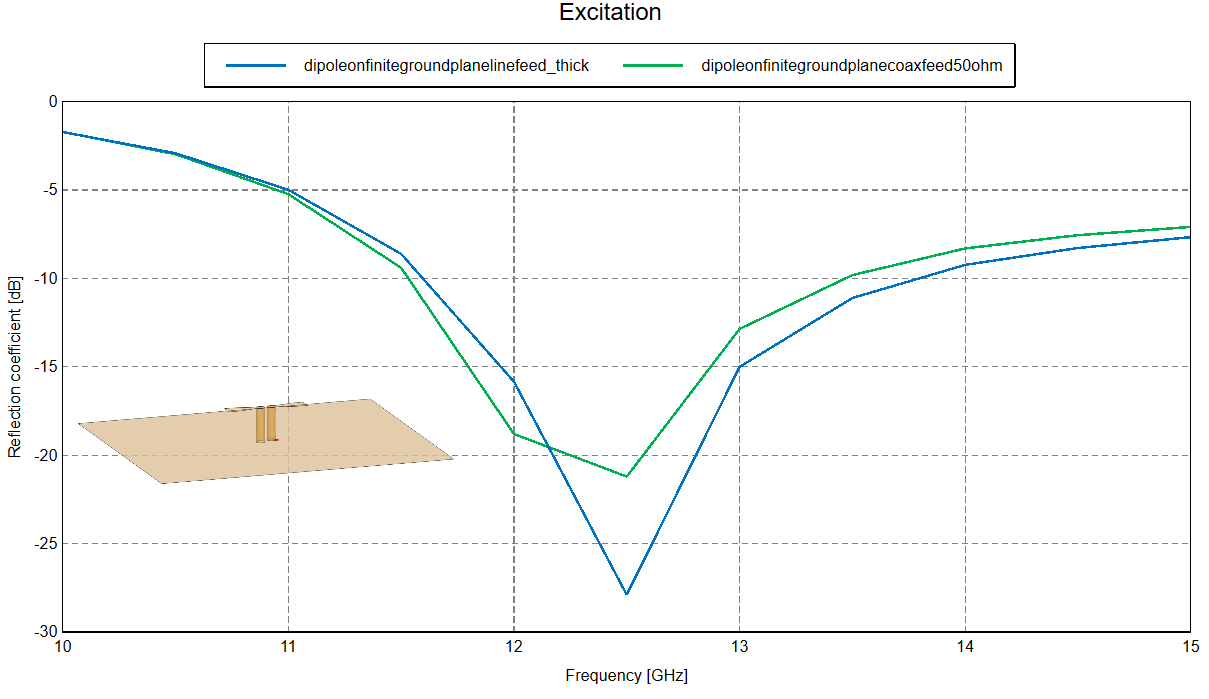
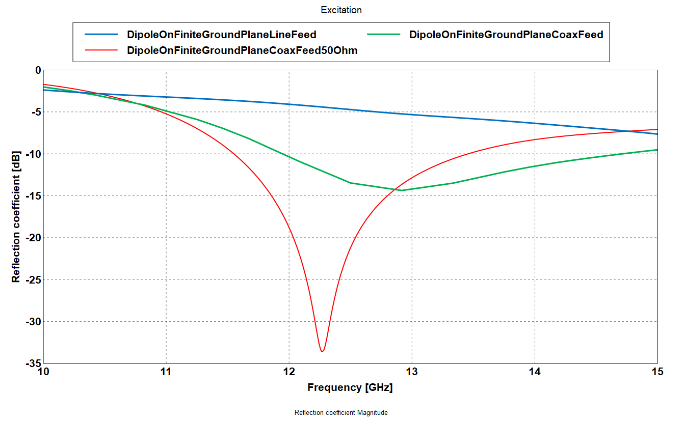
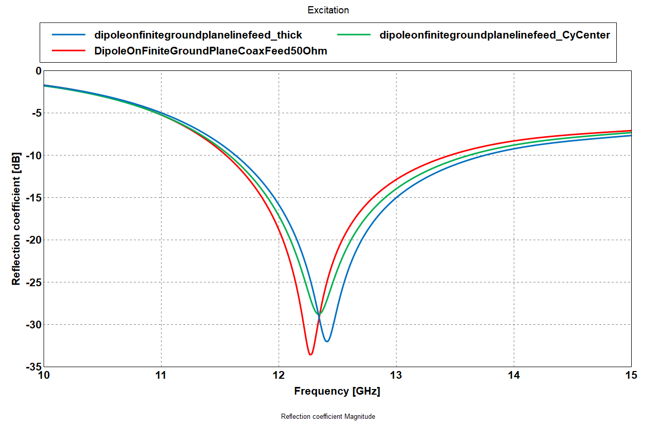
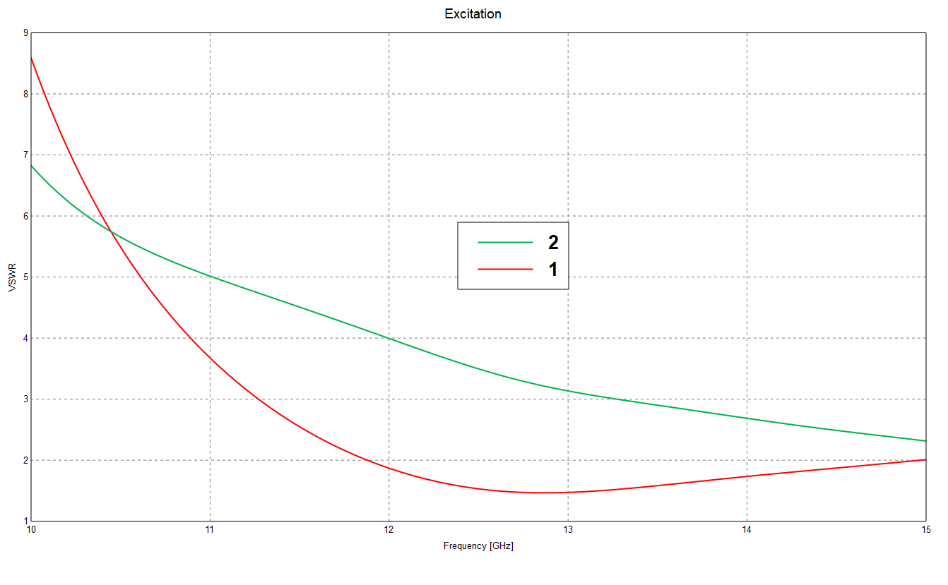
The VSWR results from the two models do not match.
I am trying to understand:
- Whether the coaxial modeling approach (Model 1) and its use as an impedance transformer are correctly implemented in FEKO.
- How to replicate the feed behavior of Model 1 in Model 2 using a line feed (without altering the substrate thickness or the distance between the dipole and the ground plane).
- I am including both model files for reference.
- Both simulations are done with the same dipole dimensions and substrate parameters.
- The aim is to simplify Model 1 while retaining the same impedance and radiation characteristics, so the simplified version can be reliably used in array-level simulations with an infinite ground.
Questions
- Is my coax modeling (circular waveguide feed + section length as transformer) approach valid in FEKO for representing a practical coaxial feed?
- If it is correct, what is the recommended way to reproduce the same feed behavior in the simplified line-feed model?
Any guidance, suggestions, or example workflows from the FEKO team or users who have handled similar feed simplifications would be greatly appreciated.
Regards,
Asif Rizwan