The Siemens Community Catalyst program was co-created with our community to acknowledge technology leaders who consistently contribute to the Siemens Community. Nominations are accepted on a rolling basis.
hello,
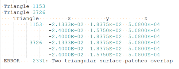
I’m getting FEKO error 2331: “Two triangular surface patches overlap” in my antenna model. It happens when meshing the patch and ground layers in my stacked geometry. Could someone explain how to fix overlapping surface meshes or misaligned solids in CADFEKO?
Hello Feko user,
The main reason you have the error 231 is that the parts of the geometry are stacted without using "Union" (under Construct tab).
You can fix the error by simply applying Union all the parts of the geometry as the attached model
(Please note that I reduced the number of the simulation frequencies.)
.
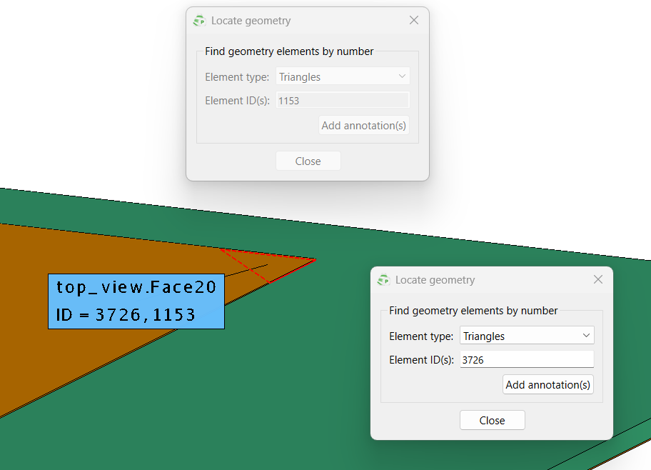
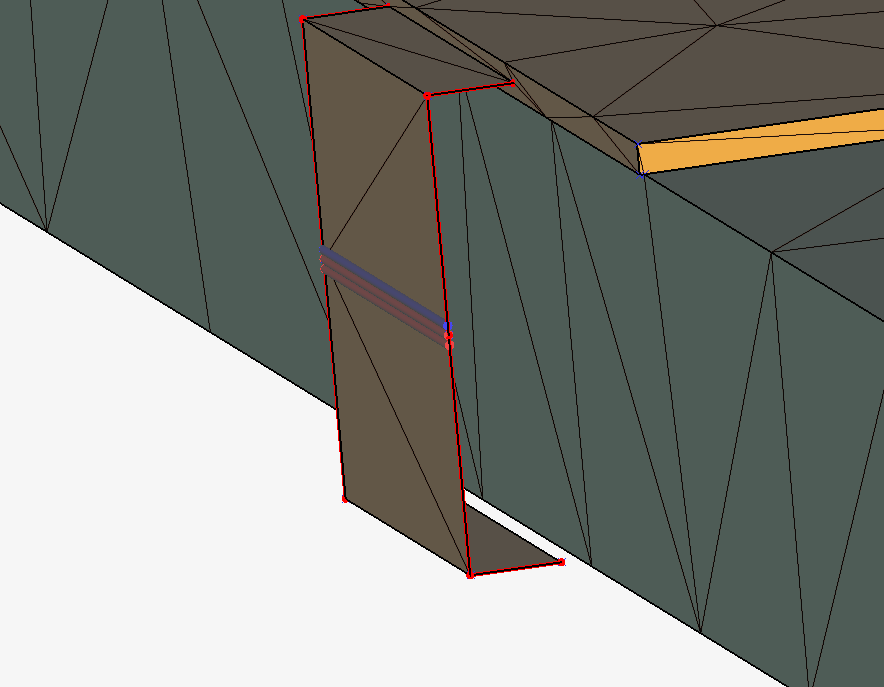
Additionally, you can check the overlapped meshes with the following steps.
2. Display the overlapped Triangle in POSTFEKO using "Find elements" under Mesh tab.
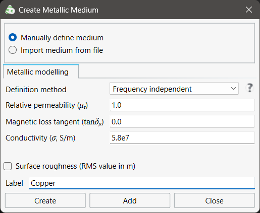
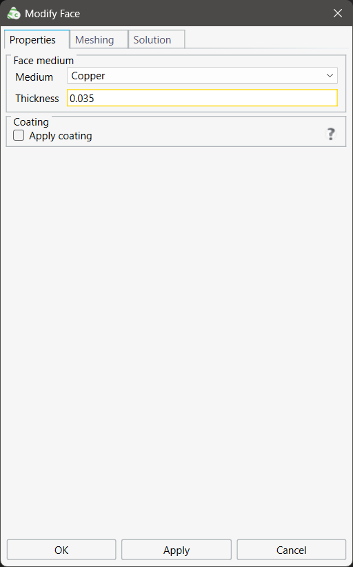
Furthermore, you might reduce the simulation time by changing the metallic cuboids (3D) with a metallic faces (2D), because the faces generates smaller number of the meshes than 3D.
Instead, you need to add a finite metallic medium (like copper = 5.8e7 S/m) and define the metallic faces by using Thickness as shown below.
For this, please start drawing the antenna with 2D parts (Rectangle, circle, ) instead of 3D parts (cuboid, cylinder, etc.) and don't foget to use "Union" in the end.
Please let me know a further question.
Best regards,
Jaehoon
thank you it helped
thank you it helped me. can explain why i am getting the error 180 while running OPTFEKO to optimize my gain using nelder mead
Do you have the error 180: A segment has neither a node nor a connection point?
If yes, this error is due to a single wire segment 'floating' in free space. The segment needs to be connected to another wire segment or to a triangle or ground plane.
ok i will check
from this image I checked my file it is just in hide, still it don't understand why?? please fix it
I can't find anything different from the model I shared. (You might know how you constructed the model.)
For your reference, I shared the solved model as below.
Please compare.
PS) I think if your goal is to optimize the antenna, I again recommend you to simplify your model with 2D as I said before.
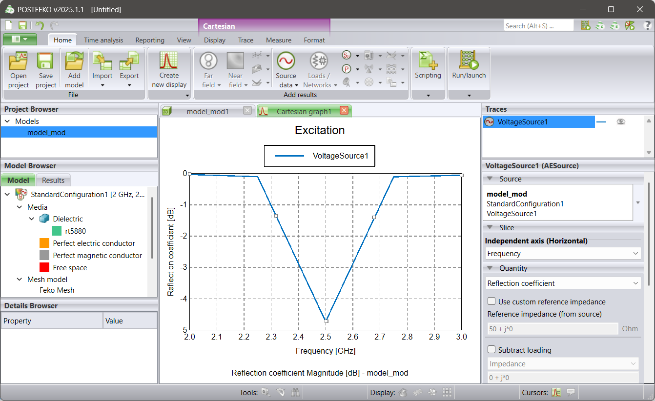
thank you but even my goal is optimization i wanna where i am going wrong with the antenna and getting reflection coefficient high which is greater than -10db….
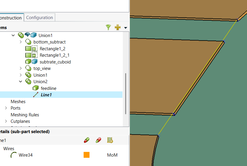
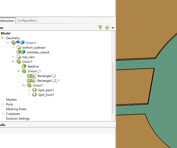
I found one physical difference between your first model and your second model.
1) The first model : You can see a line.
2) The second model - No line
yes I changed it, but don't observe any major difference even I removed that line and still problem with reflection coefficient result….anything you observed to improve the reflection coefficient please let me know…