When validating a model, there are numerous action items to verify. For example:
- Are the mass and inertia properties correct for each part?
- Are the joint and motion constraints properly defined?
- Are inputs and outputs converted to the correct units?
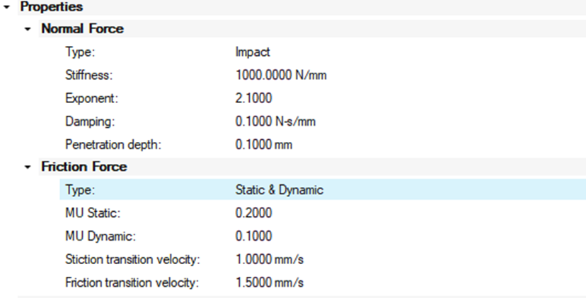
- Are the contact parameters appropriate?
- Is the mesh sizing adequate for contact simulation?
A final but essential check is to confirm whether the model converges and provides stable, reasonable results when solver parameters are tuned. Fine-tuning these parameters is a critical step in fully validating a simulation model. The primary objective is to assess whether the model remains stable and convergent under various solver settings.
To illustrate the impact of solver and contact parameter tuning, let's analyze a four-bar mechanism model. In this example, the dual slot is omitted, and the single slot comes into contact with the base.
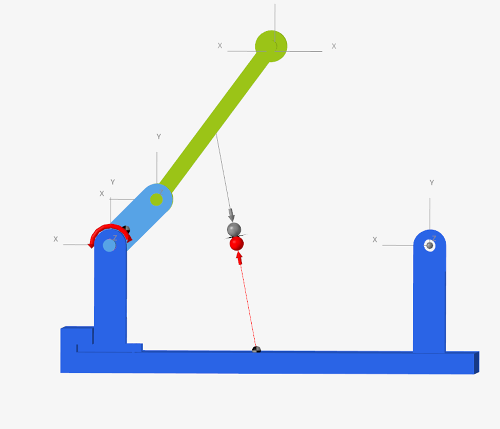
We assume that the contact properties have been correctly defined. Running the model as-is reveals that the single slot “bounces” significantly during the simulation, leading to unstable results after the initial few contacts.
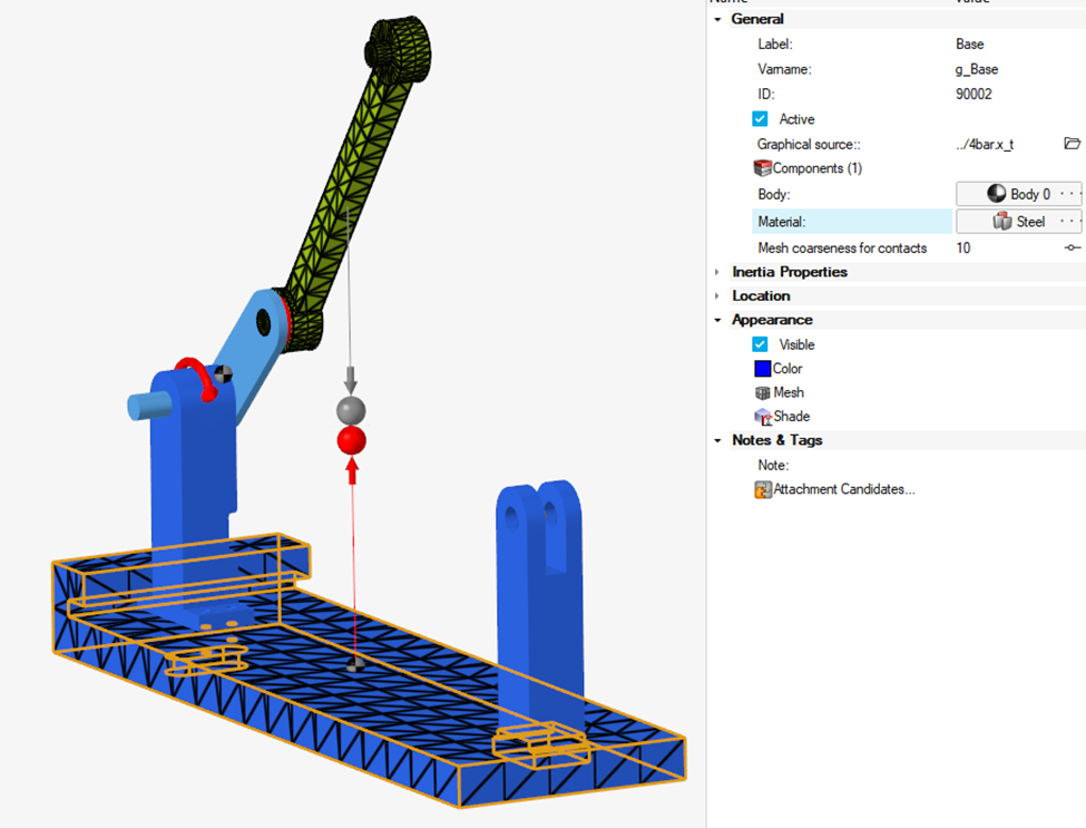
Mesh Refinement and Friction
On inspecting the default mesh, it appears to be quite coarse. We regenerate a finer mesh and enable friction.
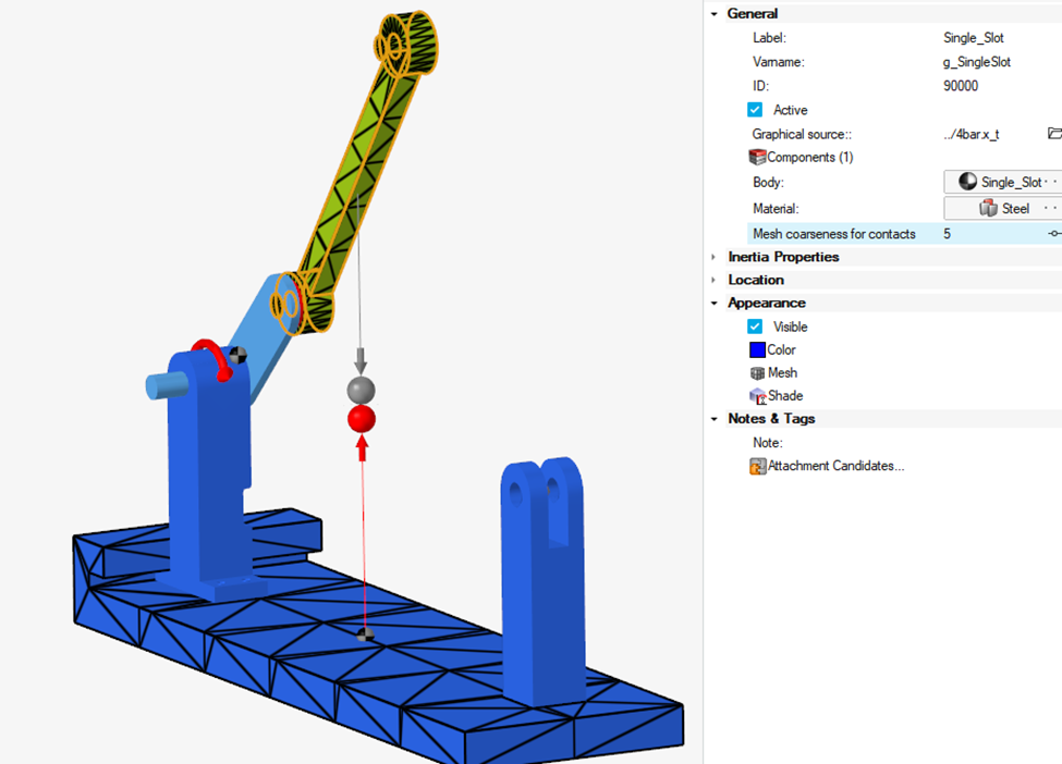
The noise is significantly reduced, and the animation appears more realistic. The next step is to fine-tune the solver settings to achieve the most stable and accurate results.
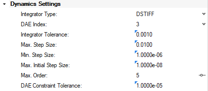
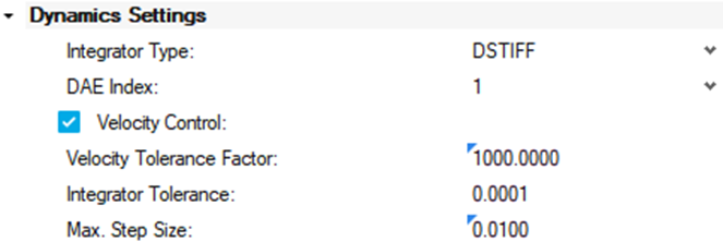
Key Solver Settings to Review
- Type of Integrator
- DAE Index (DSTIFF only)
- Integrator Tolerance
- Maximum Step Size (h_max)
- Maximum Order
Type of Integrator
In dynamic simulations, several integrators are available:
- VSTIFF, MSTIFF, and ABAM use ODE (Ordinary Differential Equations) formulations.
- MotionSolve transforms DAE (Differential Algebraic Equations) into ODEs using coordinate partitioning before solving them.
- ABAM is the only integrator specifically designed for non-stiff systems.
- DSTIFF directly solves the system in DAE form and is designed for stiff systems.
What is a stiff and non stiff system?
A stiff system includes differential equations with terms that cause rapid changes in the solution, requiring smaller time steps for stable simulation. In contrast, non-stiff systems change more gradually and uniformly.
DAE Index (DSTIFF Only)
- Index 3: Monitors displacement only. Typically faster but can result in less accurate velocity data.
- Index 1: Monitors both displacement and velocity. More accurate but computationally more expensive.
Integrator Tolerance
Defines the maximum allowed absolute error per step when computing displacements, velocities, and differential states. A tighter tolerance generally improves accuracy but may increase simulation time.
Maximum Step Size (h_max)
Controls the largest time step the integrator can take. Smaller values increase accuracy, especially for contact or discontinuous events, but can greatly increase simulation time.
Maximum Order
Specifies the maximum integration order. While higher orders provide better accuracy, they may reduce stability. For models involving contact, setting the order to 2 is often beneficial.
Simulation Comparison: Different Integrators
Using default settings, lets compare the integrators and determine the best one to go forward with. This will be based on the ability to converge, time it takes to converge and the results given.
Integrator | Time (Seconds) |
|---|
DSTIFF | 14 |
ABAM | 464 |
MSTIFF | 219 |
VSTIFF | 7 |
The integrator VSTIFF failed to converge due to the sudden impacts in the model. While integrators DSTIFF, ABAM, and MSTIFF produced similar results, with ABAM and MSTIFF nearly identical in accuracy. However, ABAM and MSTIFF took significantly longer, making DSTIFF the most efficient choice.
Tuning DSTIFF Settings
DAE Index: 1 vs 3
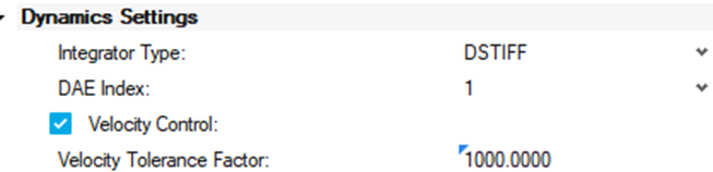
Since the model is velocity-controlled, switching to DAE Index 1 improves result accuracy at a small computational cost (16 seconds vs 14 seconds). Therefore, Index 1 is preferred for this case.
Integrator Tolerance: 1e-3 → 1e-4 mm
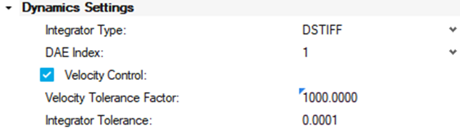
Tightening the tolerance reduced noise and brought the results closer to those from MSTIFF and ABAM. Simulation time increased modestly to 20 seconds, which is acceptable given the improvement in quality.
Maximum Step Size: 1e-2 → 1e-4
Reducing the step size led to no noticeable difference in results, but simulation time ballooned to 1116 seconds. Therefore, we reverted to the default value of 1e-2 for efficiency.
Maximum Order: 5 vs 2
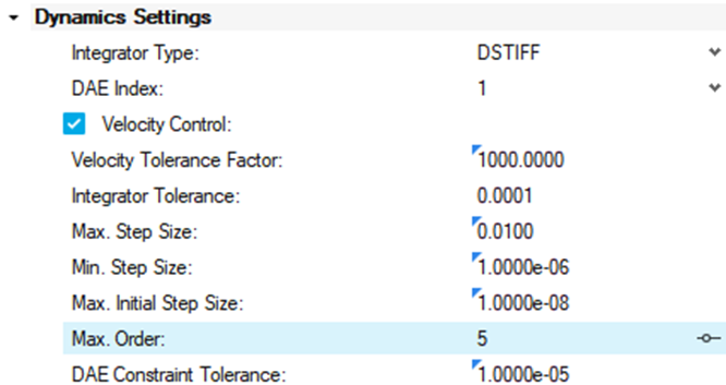

Setting the maximum order to 2 did not significantly affect results. However, it increased the simulation time to 30 seconds (vs 20 seconds for order 5). Given the similar results, we retained the default max order of 5.
Conclusion
After fine-tuning, the optimal configuration for this velocity-controlled contact model is:
- Integrator: DSTIFF
- DAE Index: 1
- Integrator Tolerance: 1e-4 mm
- Maximum Step Size: 1e-2
- Maximum Order: 5
These settings deliver a good balance between simulation time and result quality.
If we compare the original DSTIFF results to both MSTIFF and the updated DSTIFF configuration (with tighter tolerance and DAE Index 1), we observe that the new DSTIFF results closely align with MSTIFF. While there are still minor discrepancies, these are expected due to differences in how each integrator numerically solves the system equations. Nonetheless, the updated DSTIFF setup offers a solid balance between accuracy and efficiency, making it a suitable choice for this model.
Model Files
References:
Additional Resources
