This article discusses how to simulate a delta-connected PMSM in PSIM, but first let me explain some differences of these two topologies.
In a star (Y) connection, each phase winding is connected between a line terminal and a common neutral point. As a result, the phase voltage is lower than the line voltage by a factor of √3. In contrast, in a delta (Δ) connection, each phase winding is connected directly between two line terminals, so the phase voltage equals the line voltage. This means that, for the same line voltage, a delta-connected machine receives a higher phase voltage, resulting in better voltage utilization.
However, delta connection also means increased insulation requirements and potential issues with handling non-symmetric or zero-sequence currents. Since there is no neutral point, these currents cannot return through a neutral path and instead circulate within the delta loop, potentially causing heating and other operational problems.
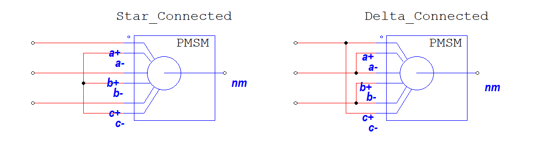
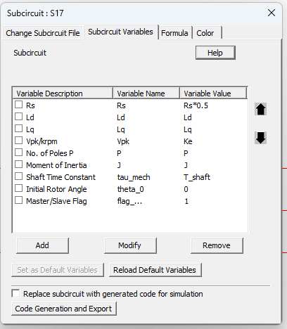
For your reference, all PMSM models in PSIM are configured with star-connected windings by default. However, there is an open-winding PMSM model at the attached simulation, which can be configured as either star or delta connected, depending on your simulation needs.
When you work with a delta connected system you have to be careful of two things.
The first one is the Vpk/krms or Ke. This is the back-EMF constant, and in PSIM is the peak line-line voltage at 1000 rpm in Y connection. The online help fails to mention, but should mention, that it’s with Y connection. So, for a delta-connected motor, Vpk/krpm will be sqrt(3) times the measured line-line peak voltage.
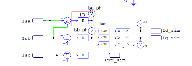
The second one concerns control issues as the current that flows through the windings is different. Specifically, as you can see in the example below, the current that flows the windings on the delta connected motor has a magnitude multiplied by sqrt(3).
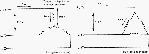
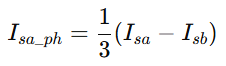
It is wrong if we just calculate the current by just dividing the line current by sqrt(3) because on this way we do not take into account the current's phase change. For this reason, when it comes to control the motor with current references, at the delta connected case, the current for each phase is calculated from the following equation:
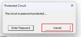
You should run the attached simulation to explore more about delta and star connected PMSM. Let me note that the Open Winding PMSM model is a custom model that is password protected, but you can use it as normal if you press "Cancel" when the password protection message pops up.
Please keep in mind that λpm is the peak flux linkage per phase due to the permanent magnets (in Webers, Wb). It’s a physical property of the motor geometry and does not depend or change with the winding configuration (Y or Δ).
What can change is how you calculate or interpret it based on the winding configuration and measurement setup.
To clarify, the Induced Voltage (per phase) from PM Flux Linkage is: Eph_peak = we * λpm → Eph_peak(per krpm) = π*P*1000* λpm/60
where P is the number of poles (not pole pairs).
With a star (Y) connected machine, the phase voltage is equal to: Vph = V_LL/sqrt(3). Where V_LL is the "line-to-line" voltage measurement. So the equation above translates to:
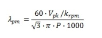
λpm = 60*Eph_peak(per krpm)/[π*P*1000*sqrt(3)]
This is the formula PSIM considers for PMSM models, and it's inside the 'Help' section.

But this only applies for star (Y) connected machines!
For delta (Δ) the voltage of each phase matches the "line-to-line" voltage measurement. So Vph = V_LL, and the equation above translates to:

In order to compensate for the fact that PSIM assumes the sqrt(3) term in the denominator, we need to multiply the measured V_LL with sqrt(3). That will give us the correct λpm for the delta connection based on the V_LL and the equation PSIM is using.
Uploaded Files: