Manufacturing Constraints for Design Optimization

JasmineB
JasmineB Altair Community Member

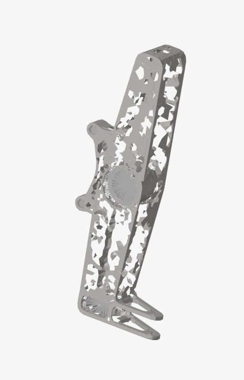
I am trying to optimize a part so that the material removed will be through holes only in one plane ie a consistent cross section. I thought that the way to achieve this is through an extrusion or a draw, but the optimization results are random nodes with some just floating in free space. In the design variable, I have set an extrusion along the depth of the part and also a mindim of 15, which should be 3 elements. I am unsure if this is being achieved as well.

Thank you for your help.

Answers

  • solon
    solon
    Altair Employee

    Hello,

    Before jumping to the optimization you have to make sure that the linear static analysis is correct.

    If you see the .out file the analysis gives a waring of excessive compliance.

    You cannot apply a BC in the dependent node of RBE3. You will be generating kinematic conditions conflict and Optistruct will try to fix it by converting the dependent degrees-of-freedom of rigid elements to independent degrees-of-freedom with PARAM,AUTOMSET (which is activated by default).

    https://help.altair.com/hwsolvers/os/topics/solvers/os/param_automset_bulk_r.htm

    From the .out file:

    One solution you could try is to convert RB3 elements to RBE2.

  • JasmineB
    JasmineB Altair Community Member

    Thank you for your response!

    I changed my constraints so that they were not on the dependent RBE3 node(just applied to the actual component), and do not see any warnings for large compliances in the out file, but am running into the same issue where the output topology does not seem to be following the draw constraint I applied to the design variable.

    Does this mean that the solver is swapping dependent DOFs still? My loads are still being applied to the dependent nodes of a RBE2, but can you do that and run an optimization? If not, are there any other issues with this set up?

  • solon
    solon
    Altair Employee
    edited March 20

    Are the linear static results (stress, displacement) as expected?

    Perform a modal analysis to ensure connectivity of the different parts.

    You can share your new model in the discussion.