Faster way to obtain average Ploss of component class MOSFET (Eon)

Vintersorg
Vintersorg Altair Community Member

Hi!

The power loss (Ploss) of component class MOSFET (Eon) is available through Ploss extra node. The help menu for this class states:

"The total loss, in watts, is represented in the form of current flowing out of this node. Therefore, to measure and display the loss, an ammeter should be connected between the nodes and the ground."

The Ploss out of this node, obtained by using an ammeter, takes a long time to converge. It takes a long simulation time frame to reach the steady state of Ploss by this approach. For this reason, my simulation is becoming extremely slow.

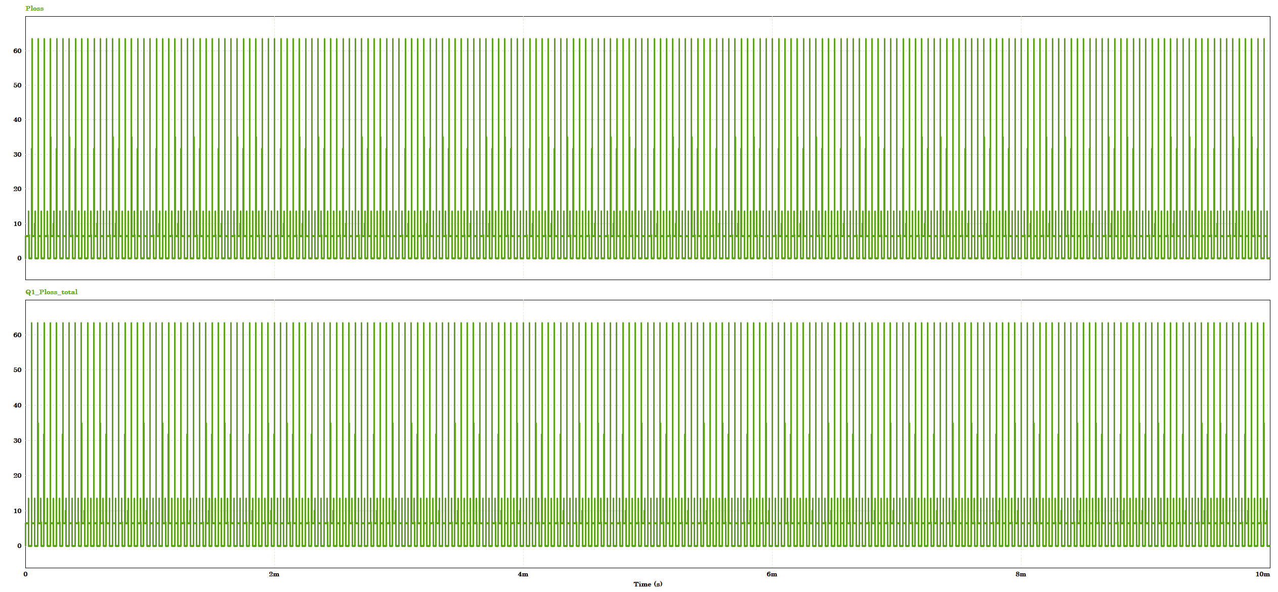
If we set to 1 (enable) the Ploss flag inside MOSFET (Eon) component parameters, we see from Ploss waveforms that the losses actually reach the steady state very fast, but it is this averaging from Ploss extra node that is taking too long to converge.

So far, I've been using a graphical approach to obtain the losses, like using cursors and getting the average power loss for one PWM cycle, but it is a manual approach and I would like to automate my simulation using a script.

Question is:

Is it possible to get Ploss instantaneous values in any way? For instance, get the instantaneous value for each simulation step, or have acces to the variable used when we enable Ploss flag and use it in the simulation schematic (or C-block?). Then, I can use a low-pass filter with my desired time constant and have the Ploss calculation to converge much faster than the ammeter approach with Ploss node.

Any suggestions? I just need a faster Ploss calculation from MOSFET (Eon) component class for an automated script.

Thanks in advance!

Tagged:

Best Answers

  • NikosDimitrakopoulos
    NikosDimitrakopoulos
    Altair Employee
    Answer ✓

    Dear @Vintersorg,

    The frequency parameter explained here Thermal Calculation - Understanding the Frequency Parameter — Altair Community applies a moving average to the losses with the specified frequency.

    For example, if you put 50Hz it will apply a 50Hz moving average calculation to the results. Now, let's say that your time step is 1e-6 sec. If you define the frequency parameter as 1/1e-6 = 1MHz, the results will provide the instantaneous losses for every step. Then you post process them as you want without needing an ammeter. Just with the flags.

    When it comes to scripting options, PSIM has introduced updates in this area. While the legacy C scripting option remains available, we have added three more modern alternatives:

    1. Compose scripting (similar to Matlab Syntax - https://community.altair.com/discussion/39388)

    2. Python scripting

    3. HyperStudy: tutorial , useCase1, useCase2

    Hope this helps!

    BR,

    Nikos

  • NikosDimitrakopoulos
    NikosDimitrakopoulos
    Altair Employee
    Answer ✓

    Dear @Vintersorg,

    Thank you for the detailed description! I now fully understand your issue. You're correct that the Ploss flag signal cannot be accessed directly inside the simulation. However, you can achieve similar results by working with the current measurement. There is just an extra step! Here's how:

    When setting up a thermal model, you need to define parameters such as the junction-to-case thermal impedance. This allows PSIM to calculate the case temperature based on the junction temperature and associated losses.

    This information is then used like this (what happens inside the PSIM thermal model):

    Now, this impedance is what "averages out" the losses you see from the current measurement.

    A quick workaround would be to edit your thermal model and set all Cauer or Foster circuit impedances as zero, like I did in the picture above. Afterward, redefine these impedances manually outside the package. By doing so, you'll gain access to the complete Ploss information directly within the package, allowing for immediate measurement.

    I am attaching a very simple example that showcases this:


    Thank you for giving me the chance to explain this interesting topic!

    Best regards,

    Nikos Dimitrakopoulos

Answers

  • VSiddhartha
    VSiddhartha
    Altair Employee

    Hi,

    Best practice is to set the Ploss flag to 1. Ploss calculation is dependent on frequency parameter. Please refer following article once:

    Thermal Calculation - Understanding the Frequency Parameter — Altair Community

    This will avoid "using graphical approach to obtain the losses, like using cursors and getting the average power loss ".

    Thank you,

    Vishwanatha Siddhartha

  • NikosDimitrakopoulos
    NikosDimitrakopoulos
    Altair Employee
    Answer ✓

    Dear @Vintersorg,

    The frequency parameter explained here Thermal Calculation - Understanding the Frequency Parameter — Altair Community applies a moving average to the losses with the specified frequency.

    For example, if you put 50Hz it will apply a 50Hz moving average calculation to the results. Now, let's say that your time step is 1e-6 sec. If you define the frequency parameter as 1/1e-6 = 1MHz, the results will provide the instantaneous losses for every step. Then you post process them as you want without needing an ammeter. Just with the flags.

    When it comes to scripting options, PSIM has introduced updates in this area. While the legacy C scripting option remains available, we have added three more modern alternatives:

    1. Compose scripting (similar to Matlab Syntax - https://community.altair.com/discussion/39388)

    2. Python scripting

    3. HyperStudy: tutorial , useCase1, useCase2

    Hope this helps!

    BR,

    Nikos

  • Vintersorg
    Vintersorg Altair Community Member

    Dear @NikosDimitrakopoulos,

    Thanks for your reply. Let me show you some screenshots of my simulation and some curvers for you to understand better the issue I'm facing with the Ploss node of MOSFET (Eon) component class.

    Here's a screenshot showing MOSFET (Eon) Q1, where Ploss node has been labeld as "PQ1".

    Ploss node (PQ1) is connected to a thermal network as suggested by the help menu description:

    I am measuring the current out of Ploss node (PQ1) (help menu states that current out of Ploss node means power loss, while voltage means junction temperature).

    When I run my simulation, the graphs below is what I get. The third graph is for variable "PQ1_loss", that comes from the current measurement out of Ploss node (PQ1). The second graph is the instantaneous power loss for MOSFET (Eon) Q1 obtained by enabling (set to 1) the flag "Ploss Flag" that is calculated by setting the frequency parameter to 1MHz (simulation step 1us).

    As can be seen in the third graph, it looks like "PQ1_loss", the power loss out of Ploss node, is not converging within the 40 ms simulation time frame, it converges only after the temperature reaches steady state (which takes a long simulation time frame to occur). Since both temperature (through voltage) and power loss (through current) come out of the same node, I believe this would be expected.

    What I really want would be to use the waveform of the second graph inside my simulation schematic. It seems that it is not possible by using the Ploss node…

    Thanks!

  • NikosDimitrakopoulos
    NikosDimitrakopoulos
    Altair Employee
    Answer ✓

    Dear @Vintersorg,

    Thank you for the detailed description! I now fully understand your issue. You're correct that the Ploss flag signal cannot be accessed directly inside the simulation. However, you can achieve similar results by working with the current measurement. There is just an extra step! Here's how:

    When setting up a thermal model, you need to define parameters such as the junction-to-case thermal impedance. This allows PSIM to calculate the case temperature based on the junction temperature and associated losses.

    This information is then used like this (what happens inside the PSIM thermal model):

    Now, this impedance is what "averages out" the losses you see from the current measurement.

    A quick workaround would be to edit your thermal model and set all Cauer or Foster circuit impedances as zero, like I did in the picture above. Afterward, redefine these impedances manually outside the package. By doing so, you'll gain access to the complete Ploss information directly within the package, allowing for immediate measurement.

    I am attaching a very simple example that showcases this:


    Thank you for giving me the chance to explain this interesting topic!

    Best regards,

    Nikos Dimitrakopoulos