How to apply a force to a rotational axis that does not rotate with it in MotionView

Garand
Garand Altair Community Member

Hi everyone

I am modeling a transmission system that includes gears. I plan to replace the gear meshing force with a pair of concentrated forces. Therefore, the application point of the forces is not on the axis of the gear.


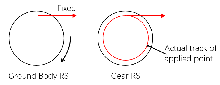
I need to ensure that the application point does not rotate with the axis, so the gear force stays at the righr place. However, once the "Action force on" option in the 'Force' is used to specify the Body, the application point rotates with the axis, leading to an incorrect result.


In fact, I tried translating the meshing force to gear center and applied torques to compensate for it. But after that, the forces is no longer collinear, creating an additional moment. I am not sure how to compensate for this moment, for the system’s shell is flexible, and adding a compensating moment would introduce deformations that should not exist.


I would like to know how to solve this problem. Thank you for your help,


Garand

Welcome!

It looks like you're new here. Sign in or register to get started.

Answers

  • GTT Adam
    GTT Adam
    Altair Employee

    Hi @Garand,

    I am unfortunately unclear as to the exact system you are trying to replicate, so can you please include pictures or animations to this question for further explanation?

    However, if you are trying to apply a force to a gear tooth and want the force to always be applied in the +X axis (for example), then you can always attach a "dummy body" at the point of application via a revolute joint and an orientation joint. The revolute connects the dummy body to the gear and the orientation joint locks it to the desired reference frame. The force is then applied to the dummy body and thus the force orientation can be controlled. Just make sure to assign a negligible amount of mass and inertia to the dummy body so it doesn't influence results.

    Hope this helps!

    Adam Reid

  • Garand
    Garand Altair Community Member

    Hi @GTT Adam

    Thank you for your answer, and sorry for the delayed reply.

    I applied axial and radial forces as you suggested, which works well. However, because the dummy body and the shaft/gear are connected by a revolute joint, they cannot transmit tangential force, so the applied force cannot drive the shaft/gear as intended.

    What I actually want to simulate is the meshing force during gear engagement:

    If we ignore the gear’s rotation, this force always acts at a fixed point in the space occupied by the gear; In the gear’s reference system, however, the point of application moves along a circular path as the gear turns. I've attached a diagram to explain this situation. Is there a way to implement this in MotionView?

    1.png

    PS: I tried using contact, but it doesn't quite fit my needs, so I switched to directly simulating the meshing force with a Force.

    Thank you for the help!

    Garand

  • GTT Adam
    GTT Adam
    Altair Employee

    Hi @Garand,

    Can you elaborate on how using contacts does not fit your needs? This is the easiest and most common implementation for this system, so I am not sure why you want to avoid it currently. The following model was created using 3D contacts and flexible bodies for balancing and vibration studies:

    motionview_gearbox.gif

    Hope this helps!

    Adam Reid

  • Garand
    Garand Altair Community Member

    Hi @GTT Adam

    Thank you for the help!

    In fact, the issue with the contact in my model isn’t due to itself. When I include the contacts in a static analysis, the solver fails to converge right at time = 0. However, if I run a transient analysis directly, it completes without any problems.

    I tried removing the contacts, and then the static analysis converges normally.

    Given this, I’d like to know how I might improve or stabilize convergence when the contact is present. Alternatively, is it possible to disable the contact for the static solve and then re‑enable it for the subsequent transient analysis (using a static+transient simulation type)?

    Regards

    Garand

  • GTT Adam
    GTT Adam
    Altair Employee

    Hi @Garand,

    Based on your description, it sounds like there might be intersecting geometry. No bodies should begin in contact as that effects the initial equilibrium of the model.

    Yes, a sequential simulation can be completed exactly as you describe. Similar to this example, a Template can be used to deactivate contacts, run the static simulation, activate the contacts, then run the transient simulation.

    Hope this helps!

    Adam Reid

Welcome!

It looks like you're new here. Sign in or register to get started.

Welcome!

It looks like you're new here. Sign in or register to get started.