Optistruct topology optimization result does not make sense

Sixuan Chen
Sixuan Chen Altair Community Member
edited October 2020 in Community Q&A

Dear all,


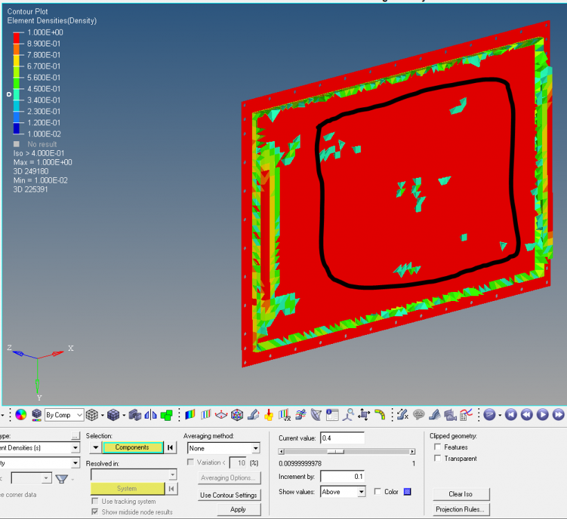
I'm working on a project as the attached image shown: We want to increase the natural frequency of the blue plate by design reinforcing components attach to the plate.

Therefore we set up a design space (green block). The objective is max mode 1 frequency of the whole model, and constraint is max 0.5 volume fraction of the design space.


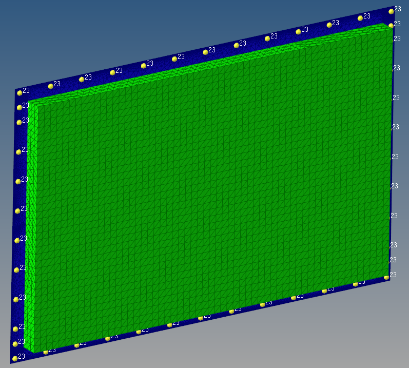
However as the second image shown:

1. Mostly only the element on the edge of the design space are left, and it's easy to understand they WON'T help to increase the plate natural frequency at all;

2. The mid elements circled in black are 'floating', meaning they are not attached to the plate at all.


Could anyone help to figure out what I may do wrong in the setup?

Thank you,

Peter


<?xml version="1.0" encoding="UTF-8"?>image.png
<?xml version="1.0" encoding="UTF-8"?>image.png

Unable to find an attachment - read this blog

Answers

  • Simon Križnik
    Simon Križnik Altair Community Member
    edited October 2019

    Hi,


    can you share the model?

  • Sixuan Chen
    Sixuan Chen Altair Community Member
    edited October 2019

    Hi,


    can you share the model?

    Should I attach the model in this post, or should I email to you separately?

  • Simon Križnik
    Simon Križnik Altair Community Member
    edited October 2019

    I'll look into it...

  • Sixuan Chen
    Sixuan Chen Altair Community Member
    edited October 2019

    I'll look into it...

    Thank you!

  • Simon Križnik
    Simon Križnik Altair Community Member
    edited October 2019

    In the model you shared the optimization problem was actually min volume fraction with a constrained frequency of the first mode. The objective and constraint should be switched as you proposed (min 1st frequency s.t. 0.5 VF).


    To make sense of topology optimization results it is useful to output ESE- strain energy. 

    <?xml version="1.0" encoding="UTF-8"?>1.jpg

    <?xml version="1.0" encoding="UTF-8"?>2.jpg

    <?xml version="1.0" encoding="UTF-8"?>3.jpg

    I have reduced the order of tetra elements and meshed the design space with hexahedral elements to save computation time. Note however the model is stiffer due to 1st order tetra- the plate should be structured hexahedral meshed for accuracy and efficiency. The minimum and maximum member size were used on topology>parameters. 

    <?xml version="1.0" encoding="UTF-8"?>4.jpg

    Refer to a similar example OS-E: 3005 Eigenvalue Maximization for alternative approaches (topography + multi frequency optimization setup).


    Unable to find an attachment - read this blog

  • Sixuan Chen
    Sixuan Chen Altair Community Member
    edited October 2019

    Thank you for the detailed answer.


    The reason I set up constraint on frequency is because we want optimized model have natural frequency more than 200Hz.


    For the example you provided, it uses topography configuration instead of topology. I have tried this approach and obtained some reasonable results.

    The topography approach will give me design that drawn beads on the plate, however, we also want to see possible solution that attach/weld additional components on the plate.


    Also I can't open the edited model you attached because of the version (mine is 2017). I made a model in creo based on the last image you attached (optimization result), the modal analysis give a natural frequency of 42Hz, which is far from enough. Could you please help to solve this issue?  


    Thanks!


    <?xml version="1.0" encoding="UTF-8"?>image.png

    <?xml version="1.0" encoding="UTF-8"?>image.png

    <?xml version="1.0" encoding="UTF-8"?>image.png

  • Sixuan Chen
    Sixuan Chen Altair Community Member
    edited October 2019

    Hi Hyperman,


    Thank you for the response, I looked into it and posted my response. Please check it out.


    Best,

    Peter

    In the model you shared the optimization problem was actually min volume fraction with a constrained frequency of the first mode. The objective and constraint should be switched as you proposed (min 1st frequency s.t. 0.5 VF).


    To make sense of topology optimization results it is useful to output ESE- strain energy. 

    <?xml version="1.0" encoding="UTF-8"?>1.jpg

    <?xml version="1.0" encoding="UTF-8"?>2.jpg

    <?xml version="1.0" encoding="UTF-8"?>3.jpg

    I have reduced the order of tetra elements and meshed the design space with hexahedral elements to save computation time. Note however the model is stiffer due to 1st order tetra- the plate should be structured hexahedral meshed for accuracy and efficiency. The minimum and maximum member size were used on topology>parameters. 

    <?xml version="1.0" encoding="UTF-8"?>4.jpg

    Refer to a similar example OS-E: 3005 Eigenvalue Maximization for alternative approaches (topography + multi frequency optimization setup).


    Unable to find an attachment - read this blog

  • Simon Križnik
    Simon Križnik Altair Community Member
    edited October 2019

    Hi,


    If you want to explore attaching hat sections stiffenerse then the mesh used is way too coarse. At least 3 elements through-thickness of sheet metal stiffener are required as optimization results are mesh denendant.  Consider using a single draw>stamp manufacturing constraint.