linear static analysis

User: "WRCpce2018"
Altair Community Member
Updated by WRCpce2018

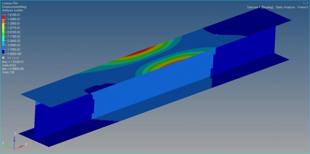
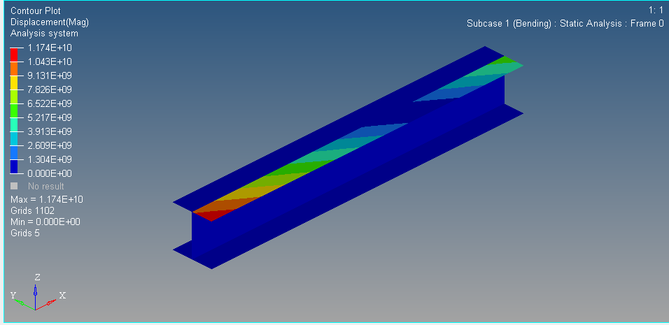
Hello there, I'm a student designing an I-beam for the SAMPE 2018-2019 bridge contest and i'm having issues with my initial linear static analysis. I believe that I modeled everything properly but my displacement contour plot doesn't look realistic. My beam consists of 4 sublaminates:top, bottom, left, and right with a ply sequence of  [0,90,-45,45] and a interface laminate consisting of 5 interfaces and interfacing the 0 degree ply between each sublaminates. Any help would be much appreciated. 


image.png.de72524030cbf097f4e5945a89e051bb.png


Unable to find an attachment - read this blog

Find more posts tagged with

Sort by:
1 - 11 of 111
    User: "Imoto"
    Altair Employee
    Updated by Imoto

    Hello @WRCpce2018


    Your model has the so many free edges, you can merge nodes using Edges panel of Tool page.

    The corrected model result is below.

    <?xml version="1.0" encoding="UTF-8"?>resolve.jpg


    Thanks,

    Imoto

    Unable to find an attachment - read this blog

    User: "WRCpce2018"
    Altair Community Member
    OP
    Updated by WRCpce2018

    Thank you so much Imoto!


    Best, 

    Wesley 

    User: "WRCpce2018"
    Altair Community Member
    OP
    Updated by WRCpce2018


    Hello Imoto, 


    Do you have any tips on how I can model my left sublaminate to have correct drape. The left sublaminate consists of elements of the left side of web and the left side of the top and bottom flanges. Currently, there are inconsistencies with the orientation of the plies within the left sublaminate which makes the model not accurate. I've seen a tutorial where you can alter the element normals within individual plies to combat this using the 'engineering application and aerospace' user profile but I have the student version which doesn't include this workbench. Any recommendations would be appreciated. 


    Thanks, 

    Wesley 


    <?xml version="1.0" encoding="UTF-8"?>image.thumb.png.c2715be5735057f4fc24ac38278739b2.png

    Unable to find an attachment - read this blog

    User: "Imoto"
    Altair Employee
    Updated by Imoto

    Hello @WRCpce2018


    You can use Orientation-Review under the Tools pulldown menu.

    <?xml version="1.0" encoding="UTF-8"?>Stu_OrientationReview.jpg


    Thanks,

    Imoto

    User: "WRCpce2018"
    Altair Community Member
    OP
    Updated by WRCpce2018

    Hi again Imoto,


    I've ran into another road block in my optimization and analysis again. I've done a free size, size and shape optimization of my current model. I was able to figure out how to import the solver decks for the free size and size optimization but I do not know how to import the optimized shape OptiStruct gave me and rerun the analysis/make additional design changes . Any help would be much appreciated. 


    Thanks in advance, 


    Wesley

    User: "Imoto"
    Altair Employee
    Updated by Imoto

    Hello @WRCpce2018


    The way to update to the free size optimization result.
    1. Open original '.fem' file in HyperMesh.
    2. Import '.fsthick' file using 'FE overwrite' option.

    <?xml version="1.0" encoding="UTF-8"?>Freesize.jpg


    Your can check the each thickness from 'Card Edit' panel.

    <?xml version="1.0" encoding="UTF-8"?>NodalThickness.jpg


    Thanks,
    Imoto
     

    User: "WRCpce2018"
    Altair Community Member
    OP
    Updated by WRCpce2018

    Thank you Imoto. What about for the shape optimization? Do I need an additional control card to output a file that includes a solver deck for the optimal shape?  


    <?xml version="1.0" encoding="UTF-8"?>image.thumb.png.9e34a22e03930e076a145febaef712e4.png

    User: "Imoto"
    Altair Employee
    Updated by Imoto

    Hello @WRCpce2018


    Almost same:-)
    1. Open original '.fem' file in HyperMesh.
    2. Import '.grid' file using 'FE overwrite' option.


    Thanks,

    Imoto

    User: "WRCpce2018"
    Altair Community Member
    OP
    Updated by WRCpce2018

    Hello again Imoto, 


    I have now finished the design and optimization phase of my beam and now I'm working on the manufacturing phase by exporting the ply shapes into CATIA to generate a CNC tool path.This is where I'm having issues now. When I export a .stp file of the ply shapes into CATIA  the dimensions of the plies are significantly smaller than to what I defined them to be in Hypermesh.  I designed my beam to have a flange width of 2.75', a length of 24', and a web height of 2' but when I measure the exported ply surfaces they are off by a factor 20 in the x-y direction. Do you know how to fix this? 


    User: "Imoto"
    Altair Employee
    Updated by Imoto

    Hello @WRCpce2018


    You can change the unit systems for exporting geometry.

    <?xml version="1.0" encoding="UTF-8"?>Unit.jpg


    Thanks,

    Imoto

    User: "WRCpce2018"
    Altair Community Member
    OP
    Updated by WRCpce2018

    Thank you for all your help Imoto!


    -Wesley