Hello Everyone,
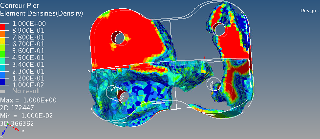
I am trying to optimize a part consisting of an isotropic material for lesser mass. I have a number of displacement constraints for the holes on the rib and have a defined Design Space.
Also, for the first time I am trying to create an optimized part which can be manufactured using some sort of press tool, meaning I have a demoulding direction.
For this, I am using the Draw-Function in the Design Variable. However I am a bit lost as to what the anchor node and the first node is an appearently this can be seen in my optimization as well. Is this the vector for demoulding? But why wouldn't it then be called N1 and N2 like normal?
The next Thing is that my part gets split during optimization, which might be mathematically sensible, but not for manufacturing and assembly.
refer to the appended.
Which leads to my two questions:
How to use the anchor and first node?
And how can I get my part to stay as one?
Best regards,
Lennart
<?xml version="1.0" encoding="UTF-8"?>