Midsurface for Sheet Metal
Hi My dear
It was already mentioned when using 2D Mesh for sheet metal's , we have to use the Midsurface in making the mesh.
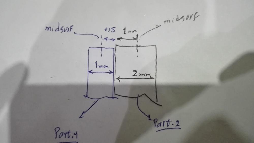
so If I'm going to creat 2D mesh for two sheet metal's with thickness of one and two millimeters , the real distance between two midsurf should be ' 1.5 mm' (In accordance with Appendix)
In the Example in the E_Book , tow Pats have thickness of one and two millimeters , While the distance of each other is about 3 mm.
Despite this, Is the analysis presented in the example correct?
bestregards
Answers
-
Hi Korosh
Altair Forum User said:Despite this, Is the analysis presented in the example correct?
Yes.
This is explained in the Fatigue e-book: (page 132 - Spot weld analysis)
The spot weld location is defined by three attributes, sheet 1, sheet 2, and the nugget. The sheets are defined by shell elements, and the nugget is defined by CWELD, CBAR, CBEAM, or CHEXA elements. The nugget can be directly connected to the shells or RBE2/3 elements can be used to connect the nugget to the shells.
The nugget needs to be modeled between two nodes of the shell parts.It seems that when the actual thicknesses of the shells are considered, the nugget should be a length of zero since the shell parts are in contact. However, the shell meshes are represented usually with zero thickness and so the nodes are placed in the middle of the theoretical thicknesses. In that case, the length of the nugget is equal to:
L = t1+t2/ 2
Where t1 and t2 are real thicknesses of the shells.Hope it is clear.
0