Problem in Boundary Conditions

RAMGANESH
RAMGANESH Altair Community Member
edited October 2020 in Community Q&A

Dear Sir,


The Problem Statement is as follows


Apply Constraints at the bottom side of ribs, Constraining translation along Y-Axis & Rotation along X & Z Axis, Keeping others free.


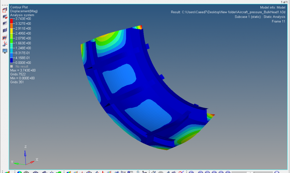
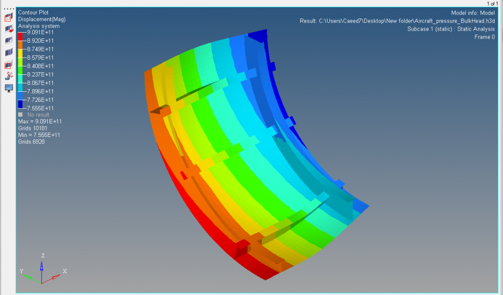
As per problem definition the displacement  value seems high .


if i arrest all Dof's the displacement  value seems ok .


Images attached below


Kindly provide your guidelines


Thanks

Ram


<?xml version="1.0" encoding="UTF-8"?>post-34029-0-59932800-1431068038_thumb.p
<?xml version="1.0" encoding="UTF-8"?>post-34029-0-66661000-1431068050_thumb.p

Tagged:

Answers

  • Altair Forum User
    Altair Forum User
    Altair Employee
    edited May 2015

    Ram,


    could you please let us know what type of analysis was given for problem statement?


    Also you need to check the orientation of the component. If you are not constraining the Z direction, then the component is free to move in -Z axis upon application of load.

  • RAMGANESH
    RAMGANESH Altair Community Member
    edited May 2015

    Dear Sir,


    The problem statement is


    Import the Geometry in HyperWorks Student Edition using the User Profile as OptiStruct. (Use Aircraft_pressure_BulkHead.iges)

    Edit the Geometry & Remove the Red Colour Edges from appropriate location, keeping the red colour edges in correct areas.

    Create 2 Components as Ribs & Hull. Divide the surfaces into respective components.

    Create Material as Steel Using E as 2.1 e+05, Nu as 0.3 & Rho as 7.9 e-09

    Create two properties with thickness as 19mm for Hull & 13mm of Ribs.

    Update the components with appropriate properties & materials.

    Create 2D shell mesh using Element size as 50.

    Apply a distributed pressure on Hull’s complete surface of 1630 MPa.

    Apply Constraints at the bottom side of ribs, Constraining translation along Y-Axis & Rotation along X & Z Axis, Keeping others free.

    Create appropriate load steps.

    Solve the model for linear static Analysis. Note down the values of Max. Von Misses Stress and Max. Displacement.

    Perform size Optimization to change the Initial thickness of Ribs & Hull & Reduce the Stress and Displacement Values.

    Create Design Variable for Ribs Using Initial Value as 13, Lower Bound as 6.5 and Upper bound as 19.5 and for Hull Using Initial value as 19, Lower Bound as 9.5 & Upper Bound as 28.5

    Create two Responses as Stress and Mass.

    Create Design Constraints on Stress for upper bound of 360N/mm2.

    The Objective of the optimization is to minimize the mass.


    The problem is solved and they changed the constraints to arrest all Dof's


    Thanks

    Ram