Optistruct Weld using Contact Tie

Andy@LamteqSolutions
Andy@LamteqSolutions Altair Community Member
edited October 2020 in Community Q&A

Hi all,


I have a question about using contact ties to attached weld elements to a structure. 


In a nutshell,


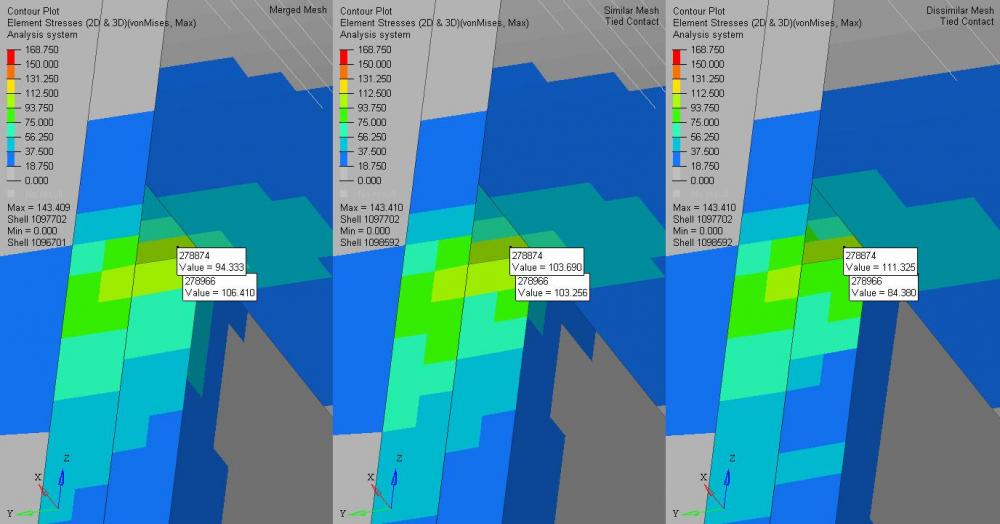
I've been asked to bring 2 models together with a dissimilar mesh and weld them. In the attached image on the left is a typical merged node to node approach with no contact - this would be our traditional approach. The middle contour plot is the same model but the weld is detached from the structure and is connected via a tied contact. The right contour plot is with a dissimilar mesh (similar to what I have been tasked with) and using the same contact tie set up as the middle contour. 


As you can see there is some variation between all three contour plots. Ideally I want to be able to use the approach in the right plot as this would cut out significant amounts of remeshing. However I do need to justify this approach.


1. Why is there such a difference between plot results?

2. Has this approach been used by others and if so why?

3. Is the contact tie approach acceptable for this application?

4. Are there any published references which can be used to support this approach?


Any help is always appreciated, I don't always get a notification when people reply so apologies if there is a delay.


Kindest regards

Andy


<?xml version="1.0" encoding="UTF-8"?>Lamteq Sol Weld Experiment.jpg
Answers

  • Adriano_Koga
    Adriano_Koga
    Altair Employee
    edited June 2020

    A couple things to check in your TIE approach is what is the master and slave selection that you've used, Even for TIE you might have some differences with dissimilar meshes. Usually the coarse mesh is master, and the finer one is the slave.

    TIE;FREEZE contact creates a zero-relative displacement condition between the connected nodes, so you might need to look at stresses there carefully. 

    Another thing is that usually is hard to evaluate stresses in these connections, as some singularities might arise. <ayne comparing the stresses in the next row of elements?


    For welded connections people use often the Hot Spot approach, and they calculate stresses in a controlled distance (toe) from the weld and then extrapolate the weld stress using some well-known formulas. (Volvo Method) 

  • Andy@LamteqSolutions
    Andy@LamteqSolutions Altair Community Member
    edited June 2020

    Many thanks Adriano,


    For some of the work we do, we do look to stress in elements at a certain distance from a weld. Alas this block of work we look to the stresses actually within the weld elements themselves against proof and fatigue... which I suspect based on what you've written cannot use  a contact tie against dissimilar mesh (bit of a shame because that would be a real game changer for us). I suspect going forward we may be able to use this approach in areas away from regions of interest.


    Interesting stuff.


    In the case above, yes the slave nodes are in the weld which is a finer mesh.


    Many thanks again

    Andy