By Richard Wood For an engineer using numerical methods such as Computational Fluid Dynamics (CFD), Discrete Element Modeling (DEM), Finite Element Analysis (FEA), or Multi-body Dynamics (MBD), modeling a physical system more often than not results in the user wanting to capture every detail about the system, be it the size and shape of objects, the physical properties of materials, the coefficients and parameters that influence mathematical models, or any motions that occur. Sometimes such motions are straightforward and can be thought of as constant velocities (e.g. the angular velocity of a rotating drum), while sometimes motions can be highly complex as a result of a combination of forces, torques, joints, pistons, etc. (e.g. an excavator digging into a pile of material).Within EDEM software, motions described in the first instance can be handled by kinematics. Complex motions described in the second instance usually require the coupling of EDEM to 3rd party MBD software to achieve the combination of accurate loads with complex motions and EDEM provides a range of coupling solutions with MBD codes such as Adams, RecurDyn and LMS Virtual.Lab Motion. For motions that lie somewhere in the middle, i.e. are driven by simple forces or torques, a user would typically make use of EDEM's Coupling Interface to write their own application and assign the motion. The Coupling Interface gives users access to a wide range of functions to interact with and control certain aspects of EDEM and an EDEM simulation. Although versatile and powerful, in order to write an application to couple to EDEM through the Coupling Interface, users will need some proficiency in C++. To make the process more straightforward for users, we have introduced a tool called the Motion Control Utility (MCU) that enables users to easily introduce motions to geometries that occur due to forces or torques being applied. The MCU means users no longer need to write and compile their own codes for applications that require geometries to have motions as a result of relatively simple forces or torques. 
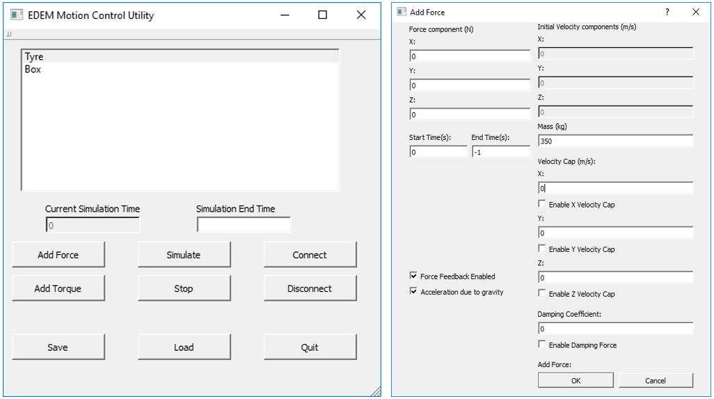
Figure 1: Graphical interface for the Motion Control Utility
The left-hand side image of Figure 1 shows what users are presented with when they launch the MCU application and connect to EDEM through the Coupling Interface. As can be seen in the main window, the names of the geometries within the EDEM simulation are loaded into the interface. The user can then add a force or torque to each geometry within the interface. Once the forces and torques have been set, they can be saved to a text file ready to load again later. The EDEM simulation can be started and stopped from within the MCU's graphical interface and can also run via the command line for headless systems. The right-hand side image of Figure 1 shows the dialog box users are presented with when adding a force to a selected geometry. In this case, the geometry of concern is set to experience a force due to its own weight. The three force entry fields in the top left of the image are where users enter the components of the force they would like to apply, in Newtons, but they do not have to simply be constant, numeric values. Time (t) can be used as an independent variable in these entry fields to apply dynamic forces, when used with some of the more common mathematical functions (e.g., trig functions, floor, exp, log) and operators (addition, subtraction, multiplication, division, exponentiation, modulus). To further highlight the need for the MCU, consider the following two examples:
- a tyre rolling on a bed of soil
- an annular shear cell test for a sample of powder
For the tyre rolling, a force can be applied to act on the tyre such that it falls under its own weight and a torque can be applied around its centre of mass to drive it forward. The reaction force provided by the material keeps the tyre at a height determined by the bed, which is constantly changing as the particles are displaced. This force in combination with the torque being applied around its center of mass drives the tyre through the bed of material. This type of behavior is not possible to capture with EDEM kinematics, which could only prescribe a motion to the tyre that would occur irrespective of how the material was behaving. For the annular shear cell, a force is applied to the top geometry, while a torque is applied to the bottom geometry. The material response of the powder sample can then be investigated due to the torque and force combination being applied. This type of behavior is arguably easier to model through EDEM kinematics than the tyre example, but it is the force, torque and material properties that give rise to an angular velocity which makes implementing a kinematic with an accurately prescribed angular velocity difficult to achieve. Put another way, an annular shear cell is a stress controlled instrument in which the velocities are a function of the imposed stresses and the corresponding macro-mechanical response of the material. These are just two examples of where applying forces and torques to the geometries of an EDEM simulation bring the numerical model dynamics closer to those of the real physical system, of which there are many, many more in the engineering world. The MCU is currently available to EDEM customers on the EDEM User Forum. There are also four examples (including the two above) on the forum to help users get started and provide inspiration for potential applications.