Product = GTAM/GSAM
Genesis® for Ansys® Mechanical (GSAM/GTAM) adds the power and versatility of Genesis® structural optimization capability to the ANSYS environment. In this article, we would like to show how to perform freeform optimization to reduce stress. Freeform optimization is a special type of shape optimization. It can split a user provided perturbation vectors into multiple perturbation vectors. The intention is to increase the design freedom with little effort from the user. GSAM can automatically create perturbation for grids on selected surfaces. The perturbation direction could be along the normal direction of the surface or a user defined direction. The maximum perturbation amount is defined by the user. During the optimization process, the grid point location is changed to achieve a better design based on the objective and constraints. Optionally the user can apply fabrication constraints such as mirror/cyclic symmetry or extrusion. Freeform optimization is typically used at the conceptual design stage to explore the potential design alternatives. However, it can also be used in fine tuning the dimensions of the model at the detailed design stage if choose ‘No’ for the freeform type. We will demonstrate these two options with the following examples.
Loading conditions
The structure is fixed at the bottom bolt holes, and a force is applied on the top cylindrical surface. The maximum stress in the original model is about 326 MPa as shown below. 
Figure 1. Loadcase and Stresses
Case 1: Use freeform optimization to find the best material distribution
The shape morphing region is defined as below. With the freeform type as ‘Yes’, each grid location is designed independently. The goal is to minimize the mass of the structure while reducing the stress to below 250 MPa. The shape change result is shown as below. The thickness is reduced at the bottom plate, and an I-beam shape is formed at the side webs. As a result, the mass is reduced 26.2% and the stress constraints is satisfied. 
Figure 2. Shape morphing region

Figure 3. Shape change result
Case 2: Use non-freeform option to fine tune the thickness of webs and plates

Figure 4. Stress result after optimization (maximum stress = 249.53 MPa)

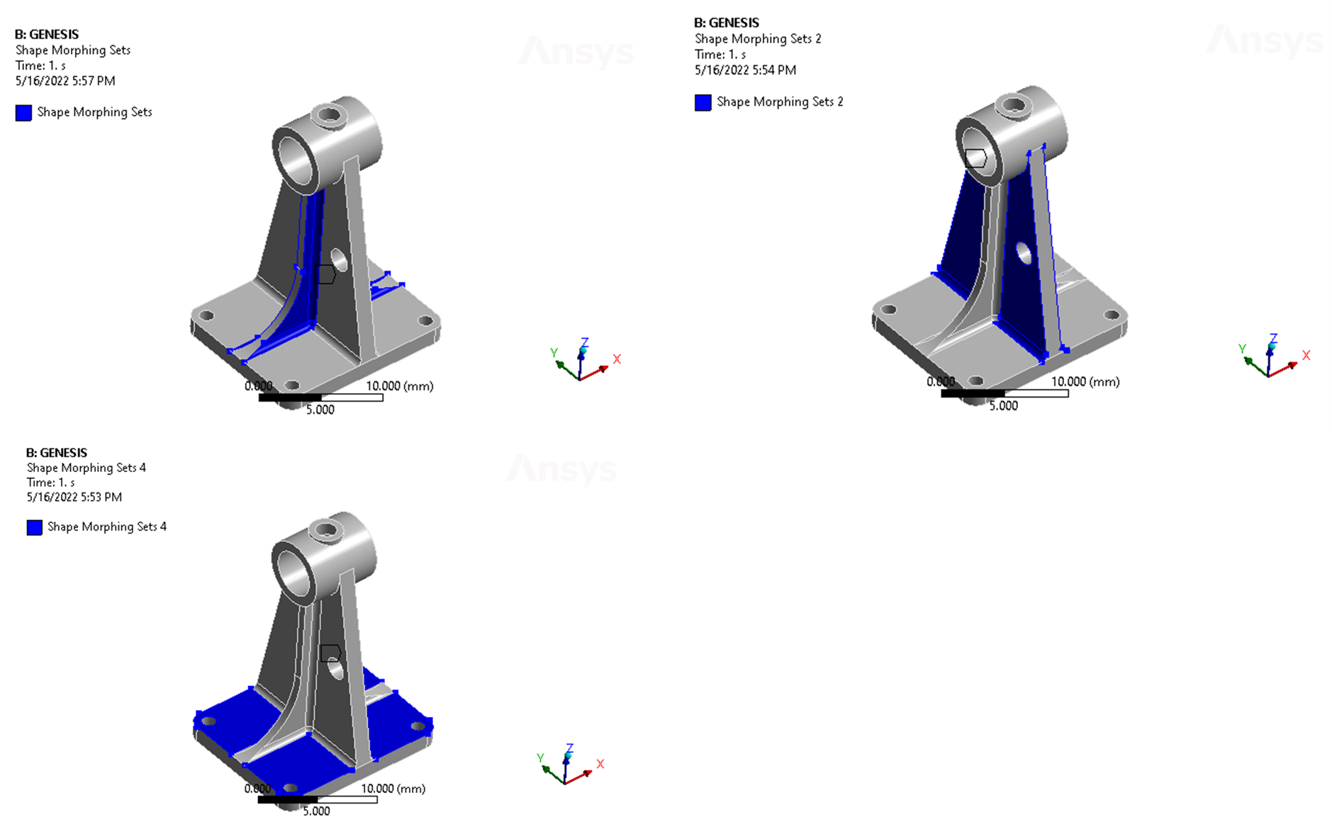
Figure 5. Shape morphing region
Three shape morphing regions are defined. With the freeform type as ‘No’, the grids on each group of selected surfaces will be designed with the same design variable. Therefore, we can design the web or the plate to have uniform thickness. The optimization problem is same as in case 1, to minimize the mass of the structure while reducing the stress to below 250 MPa.
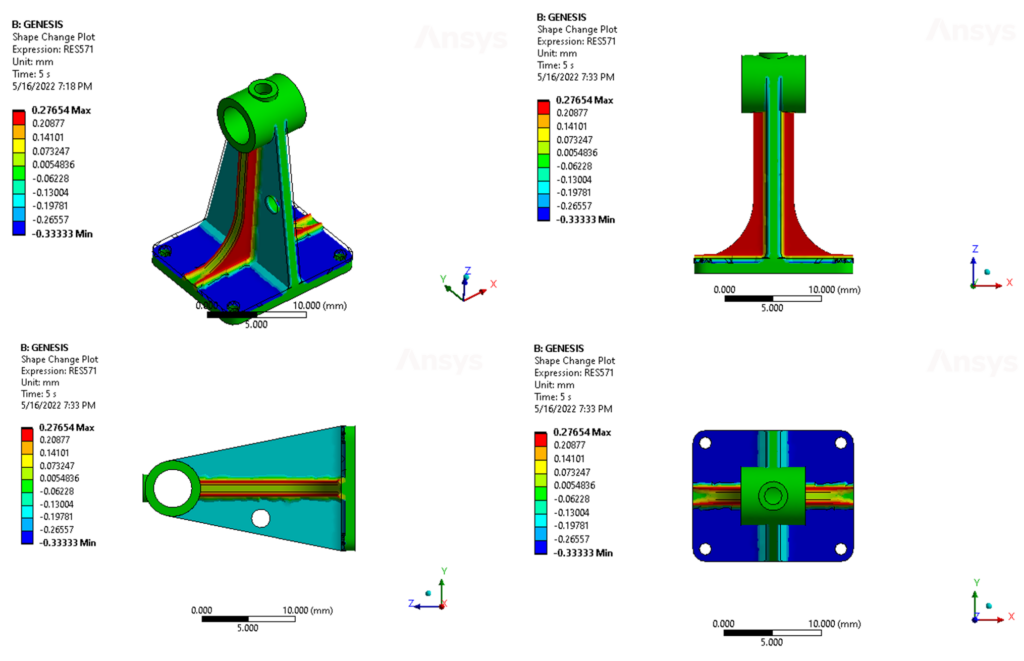
The shape change result is shown as below. The thickness is reduced uniformly 0.33 at the bottom plate, and thickness of webs is increased 0.28 and reduced 0.17 respectively. As a result, the mass is reduced 8.1% and the stress constraint is satisfied.
 Figure 6. Shape change result

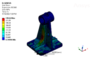
Figure 7. stress result (maximum stress = 249.64 MPa)
Summary
Comparing the shape design results, freeform gives more design freedom. The user can use freeform option at concept design stage to explore more design alternatives and seek more gain in performance or mass reduction. While non-freeform option allows the user to fine tune the thickness/dimension of the structures in the final design stage. Freeform optimization is a great tool in GSAM, which is easy to set up but also very useful for design improvement and innovation. For more details, please leave a comment below.