Software Introduction:
Altair Activate is an open and flexible integration platform for comprehensive system-of-systems simulation. It is based on a hybrid block diagram modeling environment for signal blocks, object oriented physical components, and electric and electronics systems.
Some of the physical components are based in Modelica Language and the aim of this Blog post is to cover how to use Modelica Custom Component to change and add customized component's parameters in order to expand modeling capabilities of the Modelica approach in Activate.
Problem Statement:
One of the main advantages of physical components is saving time in modeling. However, all the Modelica components from the Standard Library (MSL) work with fixed parameters. Example: Resistors work following Ohm's Law (U = R.i); Dampers work following the force equation (F = c.x'), etc.
This is an example of a Resistor-Inductor (RL) using MSL components:

Thinking about more complete and high-fidelity models, it would be useful to have the capability to customize and parametrize physical components in a systems modeling environment.
In the example above (that will be covered here) users could explore a variable resistor depending on different temperatures, and this is possible using Modelica Custom Component block (MoCustomBlock).
Solution using Altair Activate:
Modelica Custom Component (MoCustomComponent) is composed of three different sections:
- Ports: Defines Ports regarding names and block sides
- Parameters: Sets model's parameters defined in Activate (Initialization/Context)
- SimFunction: Script in Modelica language defining the Parameters, Extends, Equations and Initial Equations

Users can start modeling a Component using the block with two approaches:
- From scratch: Defining ports’ names, adding parameters, and writing the script on SimFunction sections
- Reusing the source code of a component already available when the need is to extend its capability (recommended approach and the object of this tutorial)
The streamlined workflow is copying and pasting the source code on SimFunction section, then doing the desired changes/additions on each section (Ports/Parameters/SimFunction) as shown below:

With the Setup above the final circuit is present below:

There is a video below encompassing the process of using MoCustomBlock in detail with the respective results comparing the standard approach with a customized and parametrized component (Resistor):
 https://www.youtube.com/watch?v=kIwELsWZDyk
Finally, there is an attached package with the model + detailed presentation.
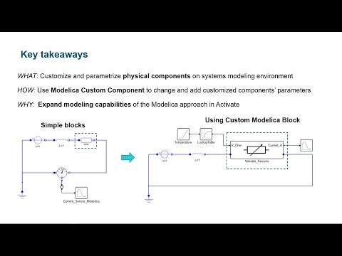
Key takeaways:
WHAT: Customize and parametrize physical components on a systems modeling environment
HOW: Use Modelica Custom Component to change and add customized component's’ parameters
WHY: Expand modeling capabilities of the Modelica approach in Activate
Interested in reducing risk, time, manpower and money with unlimited exploration for reinforcement learning? Please visit and find Altair's Multi-physics environments for your needs.