Product = GENESIS
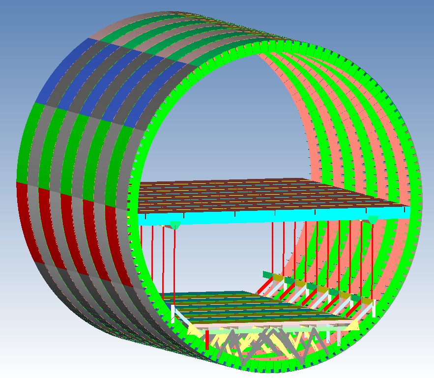
This custom-made aerospace case study demonstrates what can be done with any assembly, part, or structure of an aircraft. This is a fuselage section on which sizing (thickness changes) and topology (shape changes) were used to optimize the structure for a couple of very simple load cases; cabin pressure and passenger weight. Many other load cases can be put onto it to demonstrate the full potential of aerospace design through optimization.
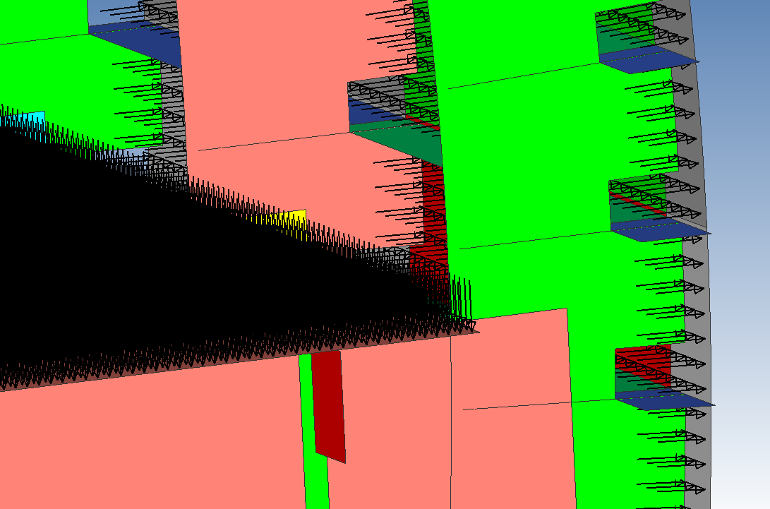
Here is a closeup of the loads applied for this optimization. Cabin pressure was set to 8.7 psi to simulate an interior of 12 psi and exterior pressure of 3.3 psi. The floor was loaded with a uniform pressure equal to 5400 lbs for this section, or approximately 30 passengers.
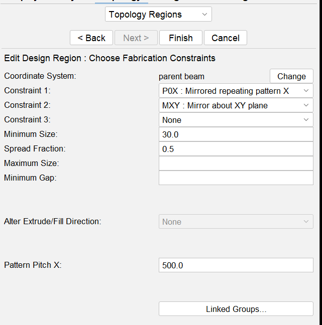
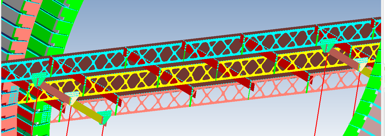
Topology was applied only to the main floor beams and controlled with pattern constraints of symmetry across the fuselage center, mirror top to bottom across the centerline of the beams, and a repeating pattern along the beams. In the current model orientation, the x-axis is across the cabin, and the y-axis is vertical. Local coordinate systems were defined to locate the center of mirroring on the beams. One beam was set as the master topology region, and the other beams were made to link to it as children for all the beams to be identical.

Here is a look at topology from a material density standpoint. The blue to red gradient indicates material contribution to the structure with blue being the lowest contributor and red the highest.
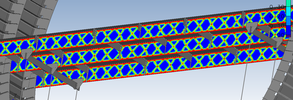
Here is the iso-surface view of the topology result. Different shapes can form by using different pattern constraints.
Sizing (thickness optimization) was applied to all components in the structure. Units are mm. 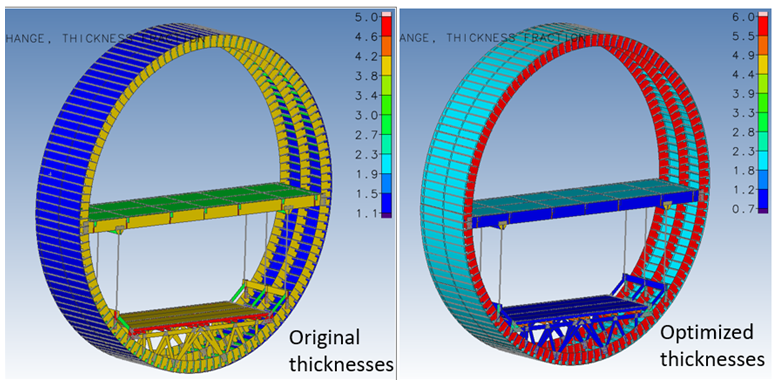
The thickness changes can be viewed as how much thickness they’ve gained or lost and also as a ratio of new thickness/original thickness. The topology result is not shown in the floor beams in this view, but the thickness change and topology result are both part of the optimization solution for those. 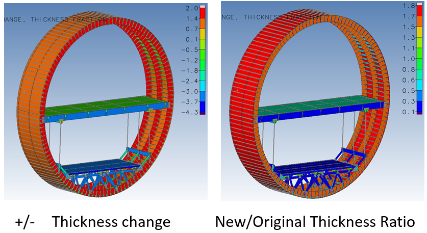 In conclusion, this simple problem demonstrates how different optimization types, in this case topology and sizing, can be used together in the same optimization. If you have any further questions or need additional information, please feel free to contact us. If you don’t currently have access to GENESIS and/or Design Studio, we can provide more details about this specific problem or assist you in obtaining our software. You can reach us by leaving a comment below.