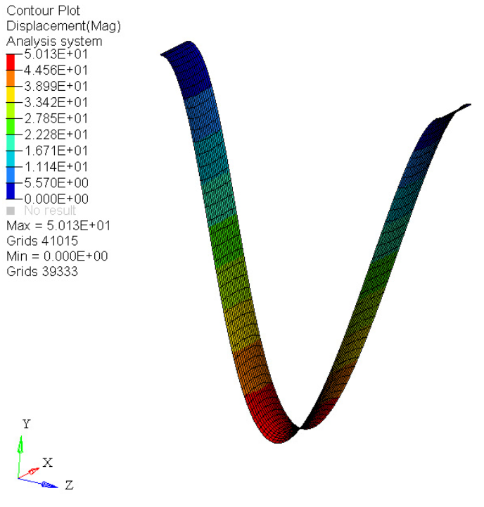
The modeling pitfalls listed below can be considered as “appetizers” with the intention of making you think (and worry) more about the model set-up. More in-depth details regarding the different modeling pitfalls are provided in the remaining chapters of Practical aspects of Finite element simulation ebook.
Geometry Simplification
In many cases, it is appropriate or even required to simplify the imported geometry in order to achieve a better mesh quality. For instance, the required minimum element size must not be smaller than x millimeters. In order to solve this (project) related requirement, small fillets may be replaced by sharp edges, as shown in the images below. Even though this simplification was/is requested, keep in mind that your FEM model now “deviates” from the initial geometry.
<?xml version="1.0" encoding="UTF-8"?>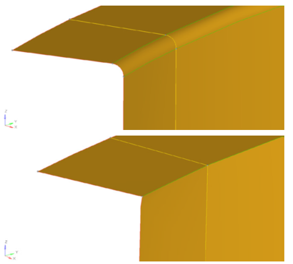
Meshing
What kind of elements are you using in your model? Why are you using this element type? Did you use this element type before?
You may mesh a thin walled 3D structure with 3D elements such as hexahedral or tetrahedral elements, or you may mesh the same structure with respect to its midsurface using 2D elements (trias or quads).
<?xml version="1.0" encoding="UTF-8"?>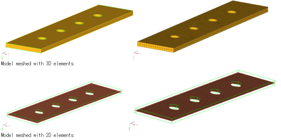
aside from the “decision” of whether to use 2D or 3D elements, there are other “uncertainties” (or even errors) related to the different numerical characteristics of quad versus trias and hexahedral versus tetrahedral elements (see the chapters on 2D and
3D meshing).
Another modeling error may be related to element size. The ultimate objective or aim is that the modeling results are independent of mesh size. Typically you need to re-run the analysis based on a finer mesh to check for convergence of the simulation results.As a rule of thumb, areas of interest should be meshed finer (smaller element size).
Of utmost importance is the element quality. Keep in mind that the elements not only “reflect” the CAD model, but eventually the analysis is based on the finite elements. Hence, any deviation from the ideal element shape (e.g. perfect quadrilateral shape in
case of a quad element) introduces numerical errors. The magnitude of such errors is generally difficult to assess.
In the model shown below, some elements are not coupled to each other (i.e. duplicated nodes exist), hence the mesh is locally incompatible. The area along the edge where the elements are not coupled is marked in red.
<?xml version="1.0" encoding="UTF-8"?>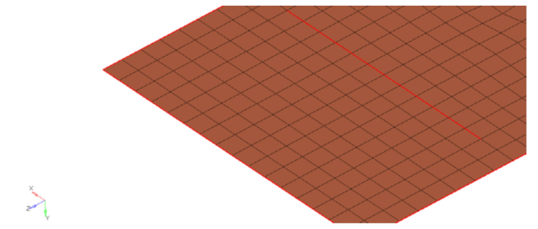
Still, the FEM program does not prompt any warning or error messages as this may be an intended model behavior. If the mesh is not intentionally detached (and the model is not checked for free edges), then this model error may remain unknown until the results are fully checked and understood. As shown in the contour plot below, the displacements are not continuous across some parts of the mesh.
<?xml version="1.0" encoding="UTF-8"?>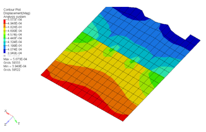
Also, keep in mind the orientation of the element normals. In the image below, a simple plate subjected to bending is shown. The stress contour plot (at the base of the elements Z1) reveals a sudden change of its sign from bending (positive) to compression (negative).
<?xml version="1.0" encoding="UTF-8"?>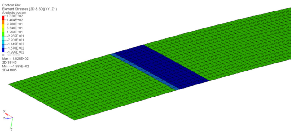
The following figure helps to understand this situation. In the green area, Z1 is located at the top of the plate (tension) while in the blue area Z1 is located at the lower side of the element (compression).
<?xml version="1.0" encoding="UTF-8"?>
Material
Inconsistencies in your unit system represent another likely source of error, i.e. mixing millimeters with meters, kilograms with tons, etc. Be especially cautious if you need to convert properties from one system to another (e.g. pound-force lbf to Newton).
There will be no warning message associated with any typos, except the “typo” will cause the entire model to “collapse” during analysis.
Boundary Conditions And Loads
Applying boundary conditions and loads, as discussed in the chapter on Boundary Conditions and Loads, are extremely prone to errors. To be mentioned exemplarily, a modeling error may
be introduced into the model by applying the constraints (or forces) to what is named temporary working nodes (in HyperMesh displayed as yellow nodes).
<?xml version="1.0" encoding="UTF-8"?>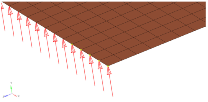
As the temporary nodes (yellow nodes in the image above are not the same as finite element nodes, it may happen that the structure is not constrained or loaded as intended.
“Ideally”, this may lead to rigid body modes (error message)or to questionable results due to an improperly constrained or loaded model.
Visualization
When visualizing results, a false sense of achievement that the analyst might experience especially after having struggled with the model, could lower his/her attention regarding details while looking at the results. Quite often, especially while you are new to FEM, one becomes blinded by contour plots. Hence, always check the magnitude of displacements and
stresses in the first step. Despite a reasonably looking displacements (or stress) contour plot, you may see displacement values in the order of 104
<?xml version="1.0" encoding="UTF-8"?>