Hi all,
I am having a bit of trouble modelling the double wishbone suspension.
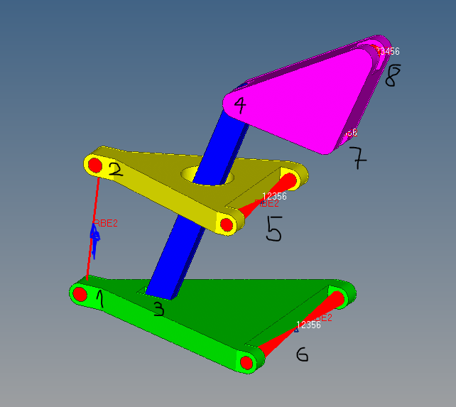
As you can see on the attached figure double wishbone suspension has quite some joints that connect the components between each other. I tried to assign the right DOF acting in this joints but the behavior doesn't seem to fit the reality.
the way this should work is:
- Joints 1 and 2 should be transforming all DOF except the rotation around 'x'. I tried to model this in the way that i connected inner nodes in the holes 1 and 2 to the central node with RBE2 constraining all DOF. Between does two central nodes there is another RBE2 which connect them in all DOF except the rotation around X. When I run the simulation joints 1 and 2 seem to be constrained in rotation around X as well. And I don't know how to fix that.
- Joints 5 and 6 seem to be working fine. Both holes on each parts are connected to the central node with RBE2 constraining all DOF to two central nodes. This two nodes are then constrained in all DOF except rotation around X. As it should be.
- Joints 3 and 4 should have similar behavior as 1 and 2 and it seem to have the same problem. Although I connect the nodes in all DOF except rotation around X, this DOF seem to be constraint as well.
- JOINTS 7 and 8 seem to be working ok as well. Joint 8 is where the spring and damper would be mounted and is moving in-plane.

So I guess the question is: How can I connect two parts between each other in all but one rotational DOF.
For easier understanding I am adding the FEM file as well.
https://ufile.io/2kusj
Thanks in advanced.