Hi Community,
I am fairly new in using MotionView and I am currently trying to simulate a simple arm of a roboter, which picks a cube and rotates 90 degrees.
After rotation, the cube should be dropped and the arm should rotate back to starting position.
Now to my first try:
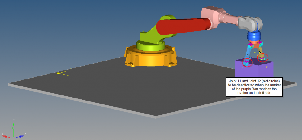
- fixed joint between arm and cube
- marker at the starting point and the end point of the rotation
I tried to solved the problem using the tutorial MV-1051 (sequential motion) but it's not exactly like I wanted to. I used a template like in MV-1051 and tried to adapt it, but it didn't work.
Could you please advise how to proceed in such a case?
Thanks in advance and if you need further information, just let me know.
Best regards,
Flo