Hello community,
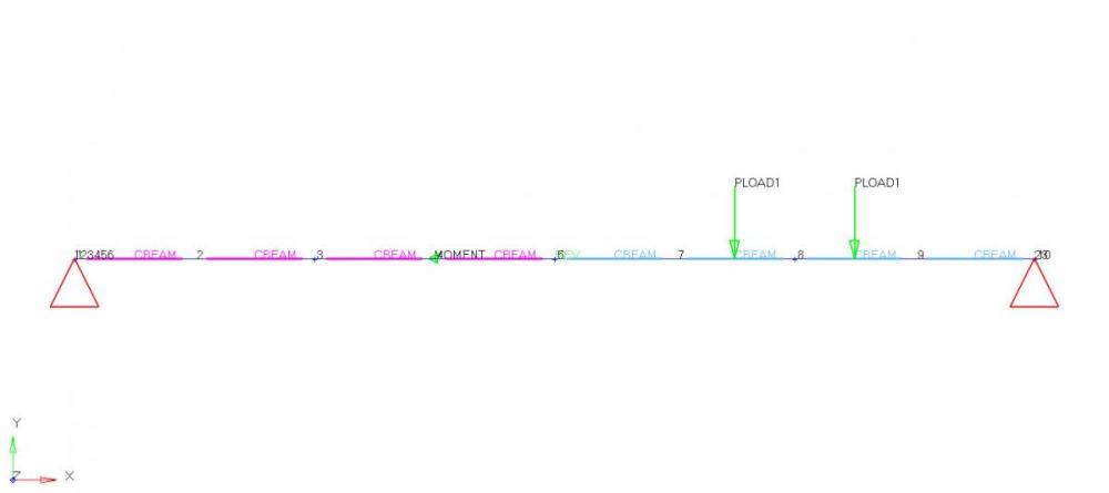
I have to do a beam analysis (see figure_1) but I don't know how to create a pin-joint in HyperMesh.
I have tried to use the joints panel in the 1D main menu page. Then I have selected the revolution joints type, because this joint type will constraint 5 dofs and will leave one rotational dof open.
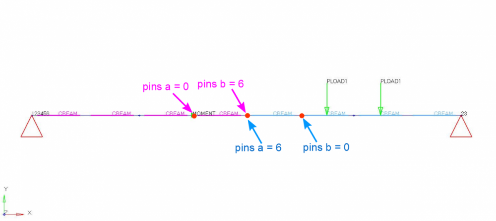
This is exactly what I want. I have selected the two terminal nodes [Grids 5 and 6 (1000;0;0)] and switched first orientation vector to z-axis (figure_2).
But it did not work because when solving the problem there is an error message:
*** WARNING # 312
In static load case 1
the compliance is negative or large 2.545087E+11
Optimization/buckling analysis cannot be performed
due to possible rigid body mode
What did I do wrong? Or is this not the right way to create such a pin-joint for this type of analysis?
Thanks in advance
Nahid
<?xml version="1.0" encoding="UTF-8"?>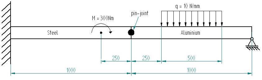
<?xml version="1.0" encoding="UTF-8"?>