The Siemens Community Catalyst program was co-created with our community to acknowledge technology leaders who consistently contribute to the Siemens Community. Nominations are accepted on a rolling basis.
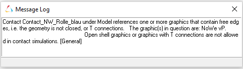
hi, i have created a 2 3d rigid to rigid contact, but when i try to run the calculation, this message log Shows for the two contacts. i have checked the model in Hypermesh, there is no free edges or red line in the so called model or geometry.
Hi Yehoo - what kind of geometry is it.? Is it a CADGraphic in MotionView ?
For contacts, from a solver perspective, the geometry needs to be clean and able to obtain a closed volume.
Hypermesh and MotionView have some differences on handling CAD graphics. It is possible that MotionView shows something as free edges, while Hypermesh does not.
You may adopt a different method of representing the graphics. If you are able to mesh the surfaces of the components in HM and export as an h3d, the same can be used as Graphics of type File. and that graphics can be used in contacts.
regards
praful
hi, i have meshed the geometry first in HM, then Export it to MotionView. Is it better to use the geometry from CAD than HM? thanks for the info though. I'll try to use the geometry from CAD instead of HM. Is the mesh Quality will be about the same, if it´s automaticly meshed by Motionview and will it effects the results?
I don't think you should use an automatic mesh from Motion View since the mesh quality is very low. I believe you missed something in your mesh. Is it possible for you to share the meshed file??
Hi,
sorry, i don't thik i can share the model publicly since it is a working Project. i have tried to work using geometry from cad, and the message log did not Show anymore when i run the model, but the model did not move at all. (This is actually my first time working with Motionview)
Ok then, I have some suggestion:
- Isolate components which you will use for the contact. perform the 2D outer mesh and delete all CAD and geometry information to avoid confusing Motion View reader. Usually, Motion View will read the mesh only if both mesh and geometry exist in the model.
- Check if there is any free edge or T connection in your mesh ( I doubt that there may be some T connection in your model).
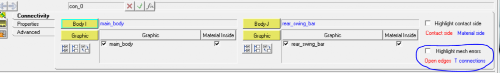
- When create contact, make sure you set up red-side (contact side) for all contact. You can use highlight contact side check box to display and check.
- Before run analysis, make sure the 'no mesh errors' is disabled as in the picture.
<?xml version="1.0" encoding="UTF-8"?>
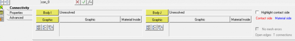
- If your contact has some problem, then the panel will appear as below:
Use 'highlight mesh errors' to check your problem. open edges will be highlighted with red color and for T connection will be blue color
Hope this help!
For the problem the model did not move. May I know which kind of input you used in your model (force, displacement, velocity, .... ) ??
for Input, i use displacement
i Change the Input and initial condition of the Motion and ist Joint to Velocity and it seems to be working. the Motion is like i imagined. i'm not sure where was the problem
Hi yehoo,
When you use displacement as your input with a single value, that means you order the system to move 'instantly' to the state of the displacement you have define at the time t=0.
Usually, it is not recommended for transient problem. You should do that in case of static analyis.
Changing to velocity is a good solution. Otherwise, if you still want to define the displacement as your desired, then you can create a .csv file to define displacement versus time data. use that file to create a curve and then use the curve to define the motion.