Electric Circuit for Brushed Dc Motor
Hello,
I am trying to simulate a DC Brushless motor in Flux2d, however I am having trouble configuring the electric circuit (Commutator for the brushes) that I require.
The motor geometry is as shown below, with the red faces being the coils around the rotor spokes.
<?xml version="1.0" encoding="UTF-8"?>
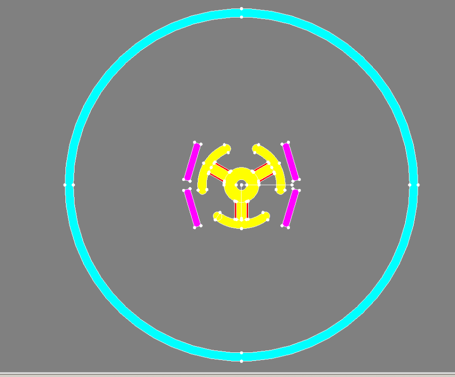
in order to define my commutator, i ran the program Circuit_collector 2D, as shown in the DC MOTOR example.
i filled the the parameters to the best of my understanding
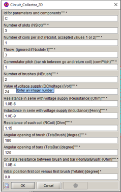
However whenever i press OK, I recieve an error message
<?xml version="1.0" encoding="UTF-8"?>
and the program leaves me with an incoherent Circuit which I dont dont how to use.
our motor configuration should b similar to this:
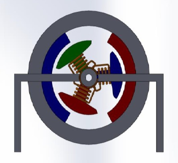
Please help us make this work. I uploaded the model as well so maybe you can open it and see for yourself what the issue is.
thank you
Answers
-
Hi,
According to the picture that you send me, I made modifications on your Flux project (see attached file). IN your project:
-
You splited the magnets in 4 parts (In the picture three are two poles and not four poles).
-
I add the frame (stator) as in the picture
-
You need to check the dimension of the new model
-
In the circuit, all the elements are not connected.
-
I create a new circuit according to the picture that you end us
-
I made a connection between the circuit and the face region.
-
I changed the orientation of the magnets
-
I create anew face regions (stator and rotor air)
If you want to create the circuit, you can use the context circuit in Flux (physics >> circuit: circuit editor context).
You will find attached your Flux project ready to solve.
Before solving the project, you need to check:
-
The dimension of the device (according to the modifications)
-
The value of the:
-
Phase resistance
-
Voltage source
-
Inductance
-
Resistance
-
The characteristic of each brush segment
-
Hope this will help.
Best regards.
0 -
-
thank you very much for the response!
however I cannot open what you sent with my student version, which is older than what you worked with (2018.1).0 -
Hi,
You are right, I use a commercial version. I create a python script to reproduce all the modifications that I done in the initial project (project that you send us).
To run the python script:
-
Open the initial project (project you send)
-
Load the python script (project >> command file: run a python file, select the script python).
Best regards.
0 -
-
Hi,
thank you for your help, we ran your script
unfortunately, there was another error,
it changed the geometry correctly , however we are not sure if we can continue, is this ok?right now we are trying to figure out how to set up the electrical circuit correctly
0 -
Hi,
Attached a screen shot of the electrical circuit that I use (it the same as in the Flux example supervisor: Flux 3D>> example supervisor >> technical tutorials: select rear view mirror motor).
Best regards.
0 -
I am trying to create a simulation similar to the example:
<?xml version="1.0" encoding="UTF-8"?>however I dont have the angle properly defined, how can I make this work?
also, it gave me an error regarding the rotor axis, I made another Face for the air in the motor with hopes it would fix the problem0 -
Hi,
I checked your Flux project, there are three mechanical sets. In your case you need to use just two mechanical sets: rotor and stator, you don’t need to use compressible (air). Then to solve the project, you need to delete the mechanical sets air and change the mechanical set in the face region air (put stator instead of air).
About the circuit, it is better if you use the macro: Circuit_Collector_2D.PFM. I create a python script to load and run the macro:
#! Flux2D 18.0
loadMacro(fileName='C:/Program Files/Altair/2020/flux/Extensions/Macros/Macros_Flux_Circuit/Circuit_Collector_2D.PFM')
Circuit_Collector_2D(id='CO_',
NSlot=3,
Ncslot=2,
throw=1,
comPitch=1,
NBrush=2,
DCVoltage=12.0,
Resistance=1.0E-6,
Inductance=1.0E-9,
RCoil=0.001,
TetaBrush=60.0,
TetaBar=55.0,
RonBarBrush=1.0E-4,
TetaIni=0.0)
With the macro you don’t need to find the brush angle (it will be done automatically). Before running the macro, you need to change the value of the TetaIni.
For the parameter TetaIni, you need to follow the steps described in the attached PT file. To solve the porejct, you need to feed just the rotor (put the magnet as air region).
Best regards.
1 -
Dear Team,
We want to calculate the EMF for PMDC brushed motor.
We are not able to create electric circuit for our problem, we have solved the tutorial of the same.
Following are the details of the DC motor
22 slots on rotor
4 Poles on stator
4 Brushes
12 Volts DC
2000 RPM
Please help us in this regards. We are using commercial License and want to develop competency in the same. Also please let us know the significance of parameters in macro to generate circuit.
Thanks,
Gaurav Purandare
0 -
Hi,
Did you tried to create the geometry? If it is the case can you share your Flux project.
Best regards.0 -
Subbarao amara said:
Dear Team,
We want to calculate the EMF for PMDC brushed motor.
We are not able to create electric circuit for our problem, we have solved the tutorial of the same.
Following are the details of the DC motor
22 slots on rotor
4 Poles on stator
4 Brushes
12 Volts DC
2000 RPM
Please help us in this regards. We are using commercial License and want to develop competency in the same. Also please let us know the significance of parameters in macro to generate circuit.
Thanks,
Gaurav Purandare
Hi Sir,
please do let us know your contact details to discuss on the same.
Thank you
Karun Teja
0 -
If you are having trouble downloading any of the files attached to this question, please try downloading one of the files attached to this reply.
0