Working with Rigids

LFSS
LFSS Altair Community Member
edited October 2020 in Community Q&A

Hello everyone. 


I'm working on a project which consists of a rod-trussed structure .I'm having some difficulties working with rigids. I have followed the Altair's student frame linear static analysis.

Since I need my SPC to be in a rigid, the configuration is this one:

<?xml version="1.0" encoding="UTF-8"?>image.thumb.png.f0de64d5f9f94c89716b284863cc3673.png
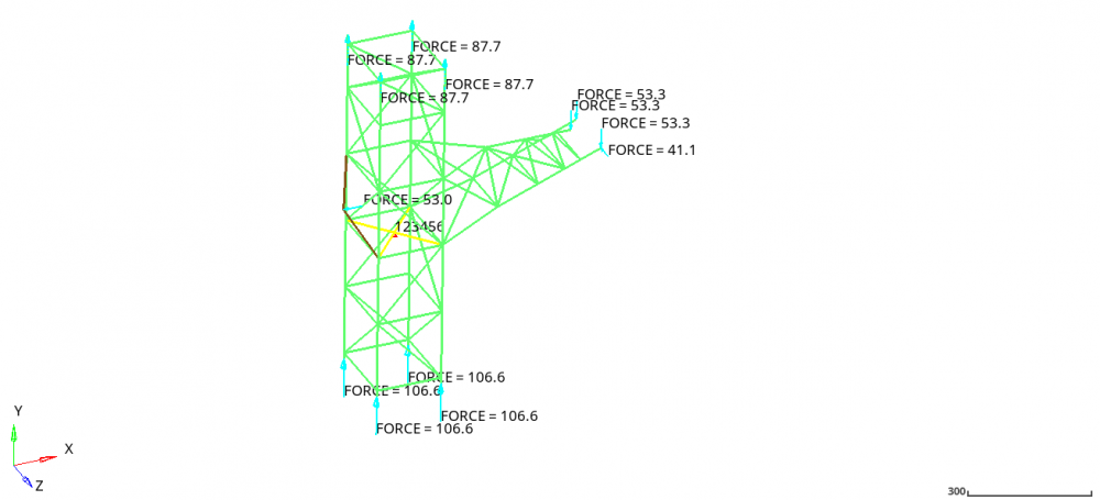
 

I am using two rigids: one for the SPC and another one for applying a force (brown line). Whenever I use the configuration above, OptiStruct says there's dependency between rigids (because the two rigids are applied to the same node). So, in order to fix that, I have tried this configuration:

<?xml version="1.0" encoding="UTF-8"?>image.thumb.png.d4fb125afd4ba97105af8da5115b2a8c.png
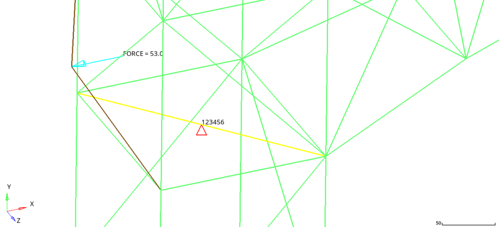
 

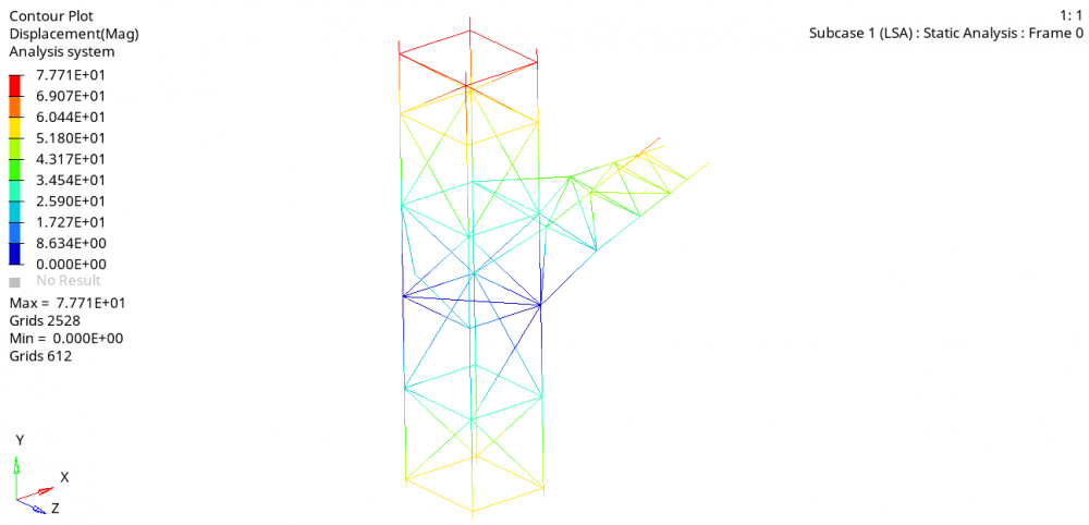
Which yields this result: 

<?xml version="1.0" encoding="UTF-8"?>image.thumb.png.9a8a733bbddd8c520d49deb984f98d31.png
 

But if I try to run a different configuration (for example, linking the SPC rigid to 3 nodes, except the one where the force rigid connects), I get this result:


<?xml version="1.0" encoding="UTF-8"?>image.thumb.png.811b57eec848c3244d82d8e2d1c6e3ea.png
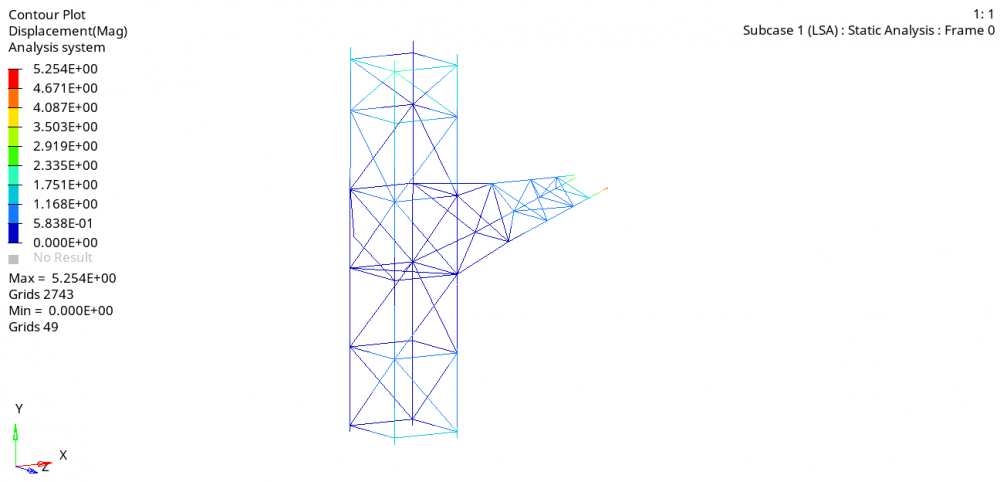
 

Which basically zeroes my displacements and stresses in the model. I have no ideia which one is giving me more realistic results and I'd could use some help trying to figure it out!


Thanks

Unable to find an attachment - read this blog

Answers

  • Adriano A. Koga
    Adriano A. Koga
    Altair Employee
    edited July 2020

    your rigid elements (yellow, and brown) are composed of only 1 rbe each, or are they made of 2 small elements each?


    If you are using 2 rigids for creating each one, make sure that the independent node is the middle one for both of them. The independent node should be the one with SPC.


    For the force it is ok. Alhogh maybe a RBE3 would be better to avoid adding stiffness.

  • LFSS
    LFSS Altair Community Member
    edited July 2020

    your rigid elements (yellow, and brown) are composed of only 1 rbe each, or are they made of 2 small elements each?


    If you are using 2 rigids for creating each one, make sure that the independent node is the middle one for both of them. The independent node should be the one with SPC.


    For the force it is ok. Alhogh maybe a RBE3 would be better to avoid adding stiffness.


    They are composed of two rigids, one for yellow and one for brown. I've made sure the middle one is the independent node for both of them, as well as where the SPC and the force is applied. What's the difference for an RBE3? is it better for my case?


  • Adriano A. Koga
    Adriano A. Koga
    Altair Employee
    edited July 2020

    RBE2 creates a kinematic condition between nodes, thus artifical stiffness is added to your model. So the dependent DOFs will follow exactly what the independent DOF does. That's why it is called rigids.

    RBE3 is used for load and mass distribution, and does not add stiffness to your nodes. Dependent node will be calculated from 'an average' of the independent nodes. Actually it depends on the weighting factors.


    Maybe sharing your model would make it easier to check what is going on.

  • LFSS
    LFSS Altair Community Member
    edited July 2020

    RBE2 creates a kinematic condition between nodes, thus artifical stiffness is added to your model. So the dependent DOFs will follow exactly what the independent DOF does. That's why it is called rigids.

    RBE3 is used for load and mass distribution, and does not add stiffness to your nodes. Dependent node will be calculated from 'an average' of the independent nodes. Actually it depends on the weighting factors.


    Maybe sharing your model would make it easier to check what is going on.

    I understand. I'll try it later today.

    I've attached the model file to the original post.

  • Adriano A. Koga
    Adriano A. Koga
    Altair Employee
    edited July 2020

    I think I didn't get what you see as a problem.


    Running your model as it is, this is what I got (just adjusting the legend a little bit, and adding a couple 'measures').

    By adding a RBE2 you're essentially imposing that the same ZERO displacement (SPC 123456) of the central node will the carried to the 3 nodes connected to it.

    Which is exactly what you got here.

    For sure you should look again at what are the BCs in your real structure and try to bring them to your model.


    There is some stress in the whole structure, although it is low compared to the stress in the red regions.


    For buckling you requested only the 1st mode, which is ok, as it is the lowest one, but you would probably want to look at others too.


    <?xml version="1.0" encoding="UTF-8"?>image.thumb.png.9473408559b54c60a2a2d2b2d524bc1f.png

    <?xml version="1.0" encoding="UTF-8"?>image.png

  • LFSS
    LFSS Altair Community Member
    edited July 2020

    That's interesting.

    So the difference between my first model (with the SPC rigid linked to 2 nodes) to my second one (SPC rigid linked to three nodes) is that in the second one I get a overstiffened structure relative to the first one, did I get it right?


    As for the buckling, thanks for the advice!


    Just out of curiosity, how do you display the tubes like that? I only get the line contour, but this one you showed here has a better visualization!

  • Adriano A. Koga
    Adriano A. Koga
    Altair Employee
    edited July 2020

    correct. 

    2nd model was stiffer thatn the 1st one.


    This image was just a display, not the real section.

    I went to Preferences and turned on visualization for 1D elements as a cylinder.

    image.png.108bd2f8da9b30c9bf98243efecb46a2.png

  • LFSS
    LFSS Altair Community Member
    edited July 2020

    correct. 

    2nd model was stiffer thatn the 1st one.


    This image was just a display, not the real section.

    I went to Preferences and turned on visualization for 1D elements as a cylinder.

    <?xml version="1.0" encoding="UTF-8"?>image.png.108bd2f8da9b30c9bf98243efecb46a2.png

    Thanks a lot man!