Using and Editing Road Files

adriannunes
adriannunes Altair Community Member
edited October 2020 in Community Q&A

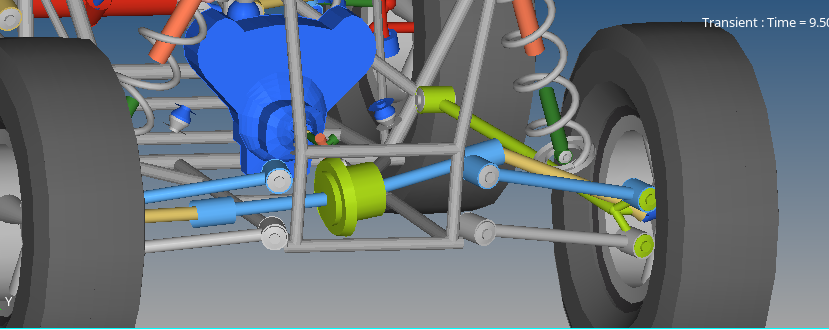
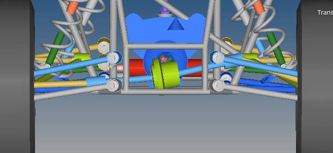
I am using the full vehicle with driver.

and have gone through the help files available.

To perform various maneuvers I have edited the .adf file for event altairdriverfile, in the .txt format and then inserted it from the event editor tab.

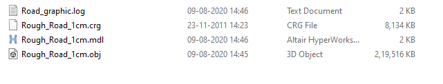
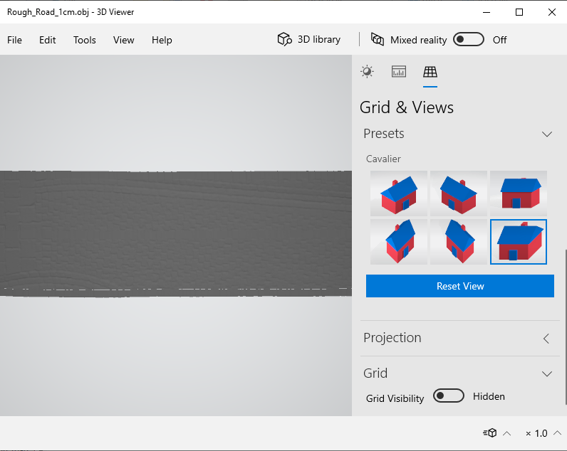
For the .adf file I copied a existing .adf file from Altair library (Straight Line Braking)  and then added the following from 3D spline road data file available in the help section.

 $-------------------------------------------------------------------------END_DATA_POINTS [OBSTACLE1] ROAD_TYPE 			= 'PotHole' COORDINATE_SYSTEM	      = 'distance' START 			    = 0.7 LENGTH 			   = 1.5 DEPTH			     = -0.007 $-------------------------------------------------------------------------END_OBSTACLE1 [OBSTACLE2] ROAD_TYPE             = 'Curb' HEIGHT                = 0.05 START                 = 0 ROUND_OFF             = 3.99805 TOP_WIDTH             = 1 EDGE_WIDTH            = 3

But it only performed the straight line braking.

How do I insert the code for it? ( I want to add a few bumps and drops) 

Welcome!

It looks like you're new here. Sign in or register to get started.

Answers

  • Felipe M Leila
    Felipe M Leila New Altair Community Member
    edited February 2020

    Hi Adrian,

    In the Altair tire entity, under properties, you can enter different road profiles.

    Try including the pothole road there and run the Straight Line Braking as usual.


    Best regards,

    Felipe.

  • adriannunes
    adriannunes Altair Community Member
    edited February 2020

    Thank you 


    1.) I tried simulating it, but it still continued to be a straight path only.

    I have edited the file as the following 

    Road Type = 2D FLAT


    $---------------------------------------------------------------------ALTAIR_HEADER
    [ALTAIR_HEADER]
    FILE_TYPE  =  'rdf'
    FILE_VERSION  =  5.00
    FILE_FORMAT  =  'ASCII'
    !
    ! road data file for TNO_flat_road
    !
    $--------------------------------------------------------------------------units
    [UNITS]
    LENGTH             = 'meter'
    FORCE              = 'newton'
    ANGLE              = 'radians'
    MASS               = 'kg'
    TIME               = 'sec'
    $---------------------------------------------------------------------definition
    [MODEL]
    PROPERTY_FILE_FORMAT    = 'USER'
    FUNCTION_NAME = 'mssticsub::ROAD'
    METHOD             = '2D'
    ROAD_TYPE          = 'flat'
    $---------------------------------------------------------------------parameters
    [PARAMETERS]
     OFFSET                      = 0
     ROTATION_ANGLE_XY_PLANE     = 180
     MU                          = 1.0
    $
     DEPTH                       = -0.05
     START                       = 10
     LENGTH                      =0.5


    (I am editing it in notepad and then saving it)

    Please point out to the mistake. 

    I want to create a pothole of the following dimension on the road.  (dimension in meters)


    2) I have used the Vehicle Tools to create graphic files for the road files I am using (CRG,RDF) so I get an idea about the road graphically.

    Is it possible to create a graphic file for the above code or for instance any .RDF or .ADF file given in the directory. How do I do it? 


    3) How do you add ramps and potholes in .CRG file?
     

  • Chris Coker_21312
    Chris Coker_21312 New Altair Community Member
    edited February 2020

    There are three possible sources of error here:


    1. Your tire data needs to be able to support non-flat road surfaces.  You have not indicated which tire model you are using (MF-Tyre, Fiala, F-tire, etc).  Tip:  look through the .log file, it will tell you what road file is being referenced, and what type of road contact.


    For example, there is a flag to set in MF-Tyre for the type of road contact you want to use.  This has to be set correctly before the road file will be properly utilized.  Research 'USE_MODE' in the MF-Tyre docs, if that's the tire model you want to use.


    2. non-flat road surfaces typically required additional licenses.  Do you have the necessary license to run non-flat roads?  (Important note:  Our built-in enhanced Fiala tire model allows users to use non-flat road surfaces, for free.  It doesn't have the same level of fidelity as tire model like MF-Swift, CD-Tire, FTire, that all require additional 3rd party licenses.)

    3. in 'road type' in the file above, you still list it as 'flat'.  So, it's going to ignore any parameters you set.  You should look at  some of the many examples provided in the installation.  There are also examples provided with documentation for the particular tire model you are using (F-tire, CD-Tire, MF-Tyre, etc).


    We currently do not provide tools for editing/modifying CRG files.  However, there are some open source tools available on the OpenCRG website.


    If you want to create graphics for an analytical road surface like you are trying to use, what I normally do is create the geometry in Hypermesh, and put a simple mesh on it, and the export it as a .h3d file, which can then be loaded directly into MotionView as a graphical entity.


    Here is an example of a pot hole road, taken from our installation folder:

    $------------------------------------------------------------------COSIN_HEADER
    [COSIN_HEADER]
    FILE_TYPE  =  'rdf'
    FILE_VERSION  =  5.00
    FILE_FORMAT  =  'ASCII'
    (COMMENTS)
    {comment_string}
    'pot_hole style road description'
    $--------------------------------------------------------------------------UNITS
    [UNITS]
     MASS               = 'kg'
     LENGTH             = 'mm'
     TIME               = 'sec'
     ANGLE              = 'degree'
     FORCE              = 'newton'
    $-----------------------------------------------------------------------GRAPHICS
    [GRAPHICS]
     ROAD_INCR = 500
    $--------------------------------------------------------------------------MODEL
    [MODEL]
     METHOD             = '2D'
     ROAD_TYPE          = 'pot_hole'
    $---------------------------------------------------------------------PARAMETERS
    [PARAMETERS]
     OFFSET                  =     0
     ROTATION_ANGLE_XY_PLANE =   180
     MU                      =   1.0
    $
     DEPTH                   =    -50.0
     START                   =  1000
     LENGTH                  =   2000


    Chris

  • adriannunes
    adriannunes Altair Community Member
    edited February 2020

    Thank You Chris


    I am using the Auto-Tires 


    FILE_TYPE                ='tir'
    FILE_VERSION             =3.0
    FILE_FORMAT              ='ASCII'
    !
    ! FILE_NAME :         TNO_car205_60R15.tir
    ! TIRE_VERSION :      MF-Tyre/MF-Swift 6.2
    ! MF-TOOL TEMPLATE :  TNO_mfswift62          $Revision: 1.15 $


    From the tire property file 


    I tried using the TNO_Plank .RDF file but still the vehicle in the H3D model shows no simulation of going over the Plank it follows the straight path only.

    (It is the original file in the library) 


    Can you please provide your secure dropbox ID. 


  • Chris Coker_21312
    Chris Coker_21312 New Altair Community Member
    edited February 2020

    Did you check the USE_MODE flag in the .tir file?  What values is given there?


    Another thing you may want to check is the orientation of the Road Reference Marker.  Sometimes this needs to be rotated about the Z axis 180 degrees, depending on the tire model and road file you are using.  Note there are probably two Markers, one for the front axle, and one for the rear axle.

  • adriannunes
    adriannunes Altair Community Member
    edited February 2020

    1. The USE_MODE value is 114.


    I tried the values as 434 and 400 also, but encountered licencing error from --- TASS Licensing Service ---.


    2. I have checked for the orientation of the Road Reference Marker it matches with my geometric axis, But they are at different heights. Is it alright to keep it unchanged. 


    3. I am also using the TNO_plank_road RDF file as the Road Property File. Will this work? 


    4.According to the USE_MODE code I want to evaluate the forces in Fz direction also, only Fx, Fy and Mx My Mz is specified. 


    Thank You 


  • Chris Coker_21312
    Chris Coker_21312 New Altair Community Member
    edited February 2020

    1. 'USE_MODE' 114 - This is part of the problem.   114 is for 'smooth road contact'  You are not going to be able to use certain types of road surfaces.  Even then, this specifies a 'point follower' road contact, which does not provide physically accurate results for short wavelength bumps.  In order to use mode 4XX, TASS requires an additional 3rd party license, as do all of the other tire model companies (CD Tire, FTire).  Per my previous post, you do not have the necessary licenses to use this tire model over a plank road surface.  You might try a polyline, but again the physics are not going to be reasonable.


    Again, please talk a look at Altair's enhanced Fiala tire model.  We support many different types of road surfaces, and there is no additional license cost.  It utilizes elliptical cam contacts, which is better than point follower, but not quite as accurate as the brush contact used by tire models like FTire or CDTire.


    To use this tire model, all you have to do is point to the tire data in the sample file directory (it will say something like 'fiala with elliptical cams' in the filename).  It is also well documented in our help.  The tire data files also have a smaller dataset, so they require less data to populate.  This kind of tire model serves as a better starting point for users just starting out with bumpy roads.


  • adriannunes
    adriannunes Altair Community Member
    edited March 2020

    1. I have started using FIALA Tire model and given RDF files in the FIALA file, I have used different USE MODE code (0,1,2,434,534) for the Simulations but the pothole is still not being simulated it follows a straight line. 


    2. While the vehicle moving forward the output shaft and the half shaft on the right side are not straight and tend to deform and form an angle like its buckling. 


  • Chris Coker_21312
    Chris Coker_21312 New Altair Community Member
    edited March 2020

    1. The FIALA tire model does not have a USE_MODE code.  Make sure you are starting with a Fiala tire dataset from the examples.  Also try rotating the road reference marker 180 degrees as explained previously.  Note, the .log file will tell you what road surface is being used.  That's always a good first double check.  If something is wrong with your road surface, it will default to a flat road.

    2. It's likely that you have not defined the outer CV joint location correctly. It needs to be located along the rotational axis of the wheel. Otherwise you will see the behavior you seem to be describing.

  • adriannunes
    adriannunes Altair Community Member
    edited March 2020

    I am using the following as the tire property file from examples and also other examples of road property file from examples


    ! HWVERSION_2019.1.0.20_Jun 28 2019_20:45:2
    $----------------------------------------------------------------units
    [UNITS]
    LENGTH                    ='meter'
    FORCE                     ='newton'
    ANGLE                     ='radians'
    MASS                      ='kg'
    TIME                      ='second'
    $--------------------------------------------------------------------------model
    [MODEL]
    PROPERTY_FILE_FORMAT      = 'USER'
    FUNCTION_NAME             = 'mbdtire::USER_FIALA'
    USE_MODE                  =  1
    CONTACT_MODEL             = '3D_ENVELOPING'
    $-----------------------------------------------------------dimensions
    [DIMENSION]
    UNLOADED_RADIUS           = 0.272        $Free tyre radius         
    WIDTH                     = 0.177        $Nominal section width of the tyre                 
    ASPECT_RATIO              = 0.6           $Nominal aspect ratio
    $----------------------------------------------------------------------parameter
    [PARAMETER]
    VERTICAL_STIFFNESS        = 47651.8      $Vertical Stiffness [force/length]
    VERTICAL_DAMPING          = 50            $Vertical Damping [force * time / length]
    ROLLING_RESISTANCE        = 0.007         $Rolling Resistance Moment Coefficient [length]
    CSLIP                     = 86748         $Logitudinal Slip Stiffness [force]; 
    CALPHA                    = 61296         $Cornering Stiffness [force / angle]
    CGAMMA                    = 3594          $Camber Stiffness [force / angle]
    UMAX                      = 1.0           $Static Friction Coefficient
    UMIN                      = 0.878         $Sliding Friction Coefficient
    RLENX                     = 0.242         $Relaxation Length in x direction
    RLENY                     = 0.597         $Relaxation Length in y direction
    ROLLING_RADIUS_FACTOR     = 0.5           $Rolling radius  =  loaded radius + ROLLING_RADIUS_FACTOR *(unloaded radius - loaded radius)
    $--------------------------------------------------------contact_patch
    [CONTACT_COEFFICIENTS]
    PA1                     = 0.671           $Coefficient of square root term in contact length equation
    PA2                     = 0.733           $Coefficient of linear term in contact length equation
    PB1                     = 1.059           $Coefficient of cube root term in contact width equation
    PB2                     = -1.1878         $Coefficient of linear term in contact width equation
    PLS                     = 0.8335          $Scaling of distance between front and rear ellipsoid
    PAE                     = 0.4382          $Half of ellipsoid length
    PBE                     = 0.302           $Half of Ellipsoid height 
    PCE                     = 1.5174          $Order of ellipsoid 
    ROAD_INCREMENT          = 0.001           $distance between contact points
    N_WIDTH                 = 4               $Number of cams along contact width 
    N_LENGTH                = 4               $Number of cams along contact length 
     

    and also used the road property file that you have mentioned as above and did the following rotations also. 

    I have checked the .log file and it shows that it has taken the pot hole profile and FIALA tire too. 

    but still I can't simulate it going through the pot hole or any cleat. 


    2. The left side half shaft and output shaft remains straight but only the right side deforms. 

    The axis of rotation of half shaft and wheel center is not the same.

    Had changed the position according to our geometry.


    Thank you 


    <?xml version="1.0" encoding="UTF-8"?>halfshaft buckling.PNG

    <?xml version="1.0" encoding="UTF-8"?>halfshaft buckling 2.PNG

  • Chris Coker_21312
    Chris Coker_21312 New Altair Community Member
    edited March 2020

    1. at this point, we'd need to take a look at the model, road and tire files you are using, if you are able to provide them.  If not, I would suggest starting with a default model, and tire, and step by step adding the Fiala tire and road.  It's really a simple workflow, with the only thing you typically have to pay attention to is the orientation of the Road Reference Marker

    2. The output shafts are clearly not in line with the differential.  I suspect you may have broken some of the parmeterization in the model.  The axis of the half shaft doesn't have to be on the axis of wheel rotation.  However, the outer CV joint must be on on the axis of wheel rotation.  Similarly, the inner CV joint locations must lie on the same axis of rotation as the differential revolute joint.


    Since you are not a university user, it may make more sense for you to reach out to your account manager at Altair, and have him connect you with our support team, where they can provide you with more hands-on assistance.

  • adriannunes
    adriannunes Altair Community Member
    edited March 2020

    Can you provide a private secure file sharing link?


    Thank you 

  • Chris Coker_21312
    Chris Coker_21312 New Altair Community Member
    edited March 2020

    you can send files to me via this link:

    https://ftam1.altair.com/filedrop/~IoZSpU


    Chris

  • Vinit Kothari
    Vinit Kothari Altair Community Member
    edited July 2020

    Hello everyone!

    I got the vehicle to follow the type of road I want it to but I don't know how to generate the graphics for the road so that I can see it. Right now I can only see my vehicle's movement and make out whether it is moving in a straight line or going over a bump. Any help will be greatly appreciated!

    Thanks!

  • Chris Coker_21312
    Chris Coker_21312 New Altair Community Member
    edited July 2020

    Depending on the version of Hyperworks you are using, and the type of Road file, you can use Vehicle Tools -> Road Tools to launch our road builder that will create a graphic system of the road.

  • Vinit Kothari
    Vinit Kothari Altair Community Member
    edited July 2020

    I am using the Hyperworks student edition 2020. I tried doing the steps you mentioned for the 3D spline road under the option altair roads still I was unable to generate the graphics.


  • Chris Coker_21312
    Chris Coker_21312 New Altair Community Member
    edited July 2020

    It's possible there is either an issue with your 3D spline road, or with the Road Tools in our software (our help for 2020 says 3D spline is supported, but this isn't a commonly used road type in my experience).  If it's possible for you to reach out to your local application engineer, and provide the file, they can send that file to our software developers.

  • Vinit Kothari
    Vinit Kothari Altair Community Member
    edited July 2020

    Okay I will reach out to them. Thanks alot!!

    However, can you please tell me what do I need to select as the output graphic model file in the road tools dialog box as I feel  I am not clear about this and I might be making a mistake there.


  • Chris Coker_21312
    Chris Coker_21312 New Altair Community Member
    edited July 2020

    The road tool creates a system definition, saves it as an .mdl , MotionView then automatically loads in this system definition.  The output graphic model file, just give it any name, and save it with .mdl extension.  The tool takes care of the rest.  Since it creates an external file, you can also load this system definition into other models as well for re-use.

  • Vinit Kothari
    Vinit Kothari Altair Community Member
    edited July 2020

    Thanks a lot for your help!!


  • Vinit Kothari
    Vinit Kothari Altair Community Member
    edited August 2020

    Hey Chris!

    I mailed the local support engineer but I haven't got any reply from him. Can you provide me with the tutorials on how to make a road in Hypermesh and import it in Motionview or else how to use the open crg files for the same. Any of the methods will do but it would be great if you could help me out learning both.


  • Chris Coker_21312
    Chris Coker_21312 New Altair Community Member
    edited August 2020

    Hi Vinit,

    Any tutorials we have on these topics would be already in our installation.  Typically you do not create a road in Hypermesh, but there is a way to do it, but that process is quite old, and requires a special script.  I'm not sure if this method is currently supported or not.

    If you have existing open CRG files, just use the Road tools.  You can just load in the .crg file, and use the default options, it will create a road and load it automatically into MotionView.  It's quite simple.


    If you search our help for 'Road Tools' you can find help on our Road Tool utility.

    It's located in our MotionView help under Vehicle Modeling -> Road Tools -> Road Graphic Builder -> Creating a Road Graphic

  • Vinit Kothari
    Vinit Kothari Altair Community Member
    edited August 2020

    Hey Chris,

    I followed your steps for creating road graphics but the road graphics were still not visible although there were .mdl and .obj files created. The .obj files when opened using 3D viewer showed the road graphics. Also, the .mdl files when tried to open were shown as invalid.

    image.png.a599cf6890a4101bad611d3229ef865d.png

    image.png.ceff4b7ffb483676d8bf4613e5bbdeca.png

    How do I import this road into motionview. Even the rdf files already present with the installation made the same files and were visible using 3D viewer. Please help as I am quite close to getting this issue solved!!!

  • Chris Coker_21312
    Chris Coker_21312 New Altair Community Member
    edited August 2020

    Hi Vinit-

    Again, since you are not a university user, please contact your local support organization.  They can assist you more directly.  There may be a problem with the software, or a problem with your source files.  I would first recommend trying out the process with one of the default road files are are included in the software install.


    It appears that you are doing everything correctly, so without access to the files you are using, it's really impossible to really provide much more assistance.  sorry you have been struggling with this.  It's usually quite easy.

  • Vinit Kothari
    Vinit Kothari Altair Community Member
    edited August 2020

    Hey Chris!

    I figured out something different in my version of MotionView and I think this may be the possible reason for the error in visualization. As soon as I select the road in road tools to create graphics, it shows output graphic created but there is nothing to be seen under road graphics column as shown below. So is it that I have to make any changes over this section to get the desired output like add a ground body or anything.

    <?xml version="1.0" encoding="UTF-8"?>image.png

  • Chris Coker_21312
    Chris Coker_21312 New Altair Community Member
    edited August 2020

    Vinit-

    Again, please follow up with the issues you are having with your region's support organization, so they can get the appropriate files from you, and get software development involved.  Make sure you tell them which version of Hyperworks you are using, computer hardware and OS information, etc.


    Make sure you have tried out the process with one of the included road files in the software installation first, to rule out a problem with the road data you are using.

  • Vinit Kothari
    Vinit Kothari Altair Community Member
    edited August 2020

    Sure Chris. Thanks alot!!

Welcome!

It looks like you're new here. Sign in or register to get started.

Welcome!

It looks like you're new here. Sign in or register to get started.