Cabin Thermal Simulation

nvn
nvn Altair Community Member
edited October 2020 in Community Q&A

Hi,


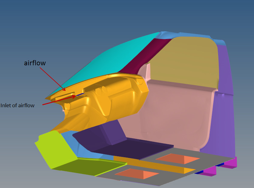
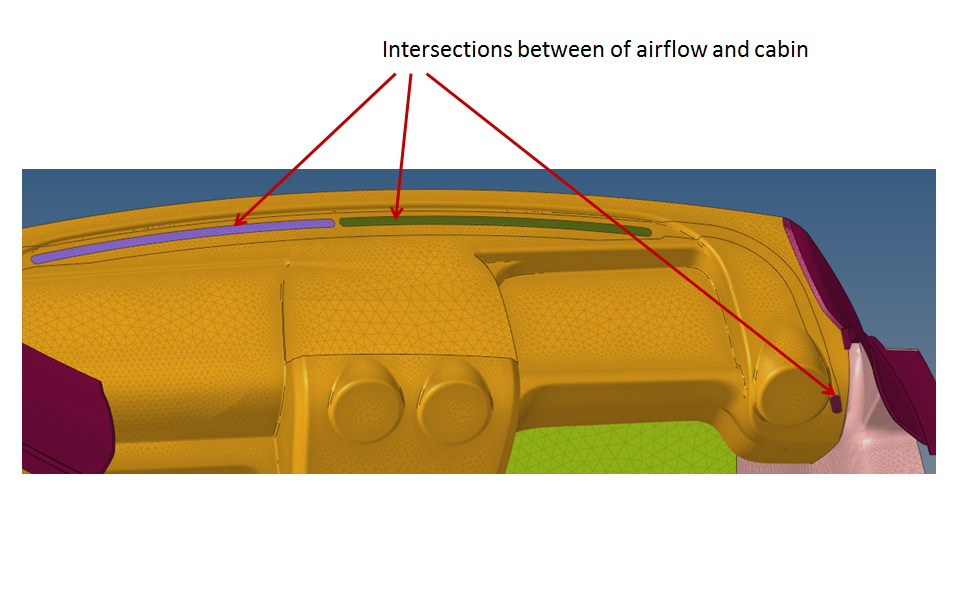
i have to simulate the airdistrubiton on the windshield, so i modulated a cabin with a airflow. So i have 2 volume, how can i define the intersection(surface) between airflow-volume and cabin-volume ? I have set on the  Type: wall and  wall function : None , is that correct ?


<?xml version="1.0" encoding="UTF-8"?>bild5.PNG
<?xml version="1.0" encoding="UTF-8"?>bild4.PNG

Tagged:

Answers

  • Altair Forum User
    Altair Forum User
    Altair Employee
    edited November 2018

    hello!

    i am not cfd specialist.

    you do great job! it's interesting issue. is it windshield defrost?

    you should make 2 volumes.

    first are tubes

    second is cabin.

    and the WALL should be common part for tube and cabin (mesh node to node).

    <?xml version="1.0" encoding="UTF-8"?>image.thumb.png.dd59a42d4cf8f7e18704ac024beadc2c.png

  • nvn
    nvn Altair Community Member
    edited November 2018

    no, it is not windshield defrost, we want to construct side-outlet  from the airflow, and bevor we want to see, how the air will distribute,( i mean the direction of the flow), i think in hypermesh it worked so, but by acusolve, i dont know how can i define the surface (simple boundary condition)?

  • acupro
    acupro
    Altair Employee
    edited November 2018

    You really only need one volume - since it's all air.  If you do have two, then you need to deactivate (turn off) Simple Boundary Condition on any surfaces between the two air volumes.

  • nvn
    nvn Altair Community Member
    edited November 2018

    which global mesh size (absolute) is suitable for this model ?

  • Altair Forum User
    Altair Forum User
    Altair Employee
    edited November 2018

    which global mesh size (absolute) is suitable for this model ?

    you can't use one size fo all model.

    as i know you should use min/max and grow rate parameters.

    and my question to @acuprowhy can't i use several volumes separated by wall?

  • nvn
    nvn Altair Community Member
    edited November 2018

    i used on hypermesh at 2D-Mesh min/max. mesh size , but i can define by AcuSolve a global mesh size, because i have one volume, or not ? Additionally i can define curvature parameters, but my question is, is 0,02 m suitable for this model?


    <?xml version="1.0" encoding="UTF-8"?>Unbenannt.PNG

  • Altair Forum User
    Altair Forum User
    Altair Employee
    edited November 2018

    i used on hypermesh at 2D-Mesh min/max. mesh size , but i can define by AcuSolve a global mesh size, because i have one volume, or not ? Additionally i can define curvature parameters, but my question is, is 0,02 m suitable for this model?

    i haven't done mesh fo cfd, i haven't ever worked in acusolve.

    as for me the best way to try=) do cube, and do diffrent approach/mesh size.=)

  • nvn
    nvn Altair Community Member
    edited November 2018

    Hey,

    which tools in AcuFiedView can i visualize the velocity-variation on the windshield? i used boundary surface but it isnt worked. The sectional images below was made with coordinate surface.

    <?xml version="1.0" encoding="UTF-8"?>bild.PNG

  • acupro
    acupro
    Altair Employee
    edited November 2018

    Boundary Surfaces in AcuFieldView can be displayed with contours (such as Smooth or Constant) or with Velocity Vectors as shown on the Coordinate Surfaces.  If you want contours of Velocity Magnitude rather than individual components, if you don't have Velocity Magnitude as a scalar, you can use the Fv icon to create your own Variables.

  • acupro
    acupro
    Altair Employee
    edited November 2018

    If two fluid volumes are actually separated by a physical wall, then, yes, you would use a surface with a Wall Simple BC.  (And if it's a zero-thickness surface, you need to use the 'Split Internal Faces' after creating the initial mesh in order to have distinct nodes on either side of that physical wall.)  In this case, it was difficult to tell exactly, but it looks like there is a geometric surface between fluid volumes, but maybe that geometric surface isn't actually a physical wall in reality.

  • acupro
    acupro
    Altair Employee
    edited November 2018

    nvn - The Global mesh size applies to the entire model - so think of that as your largest mesh size.  Then to get smaller mesh elements as needed to resolve geometry better, you have Volume, Surface, Edge Mesh Attributes.  You also have Zone Mesh Attributes where you can control mesh in a volumetric region/zone in the model that is independent of geometry.  You should probably contact your local Germany support as well.

  • nvn
    nvn Altair Community Member
    edited November 2018

    Boundary Surfaces in AcuFieldView can be displayed with contours (such as Smooth or Constant) or with Velocity Vectors as shown on the Coordinate Surfaces.  If you want contours of Velocity Magnitude rather than individual components, if you don't have Velocity Magnitude as a scalar, you can use the Fv icon to create your own Variables.

    where can i find the Fv icon ? can you tell me execution?

  • nvn
    nvn Altair Community Member
    edited November 2018

    nvn - The Global mesh size applies to the entire model - so think of that as your largest mesh size.  Then to get smaller mesh elements as needed to resolve geometry better, you have Volume, Surface, Edge Mesh Attributes.  You also have Zone Mesh Attributes where you can control mesh in a volumetric region/zone in the model that is independent of geometry.  You should probably contact your local Germany support as well.

    thanks a alo, its working very good now. i have problem only by visualisation :/ I want to illustrate in this form see below..

    <?xml version="1.0" encoding="UTF-8"?>Streamlines-plots-for-the-airflow-coming-out-of-the-defroster-duct-in-defrost-mode-of.png

    <?xml version="1.0" encoding="UTF-8"?>and-6-show-the-streamlines-based-on-the-velocity-values-from-the-front-and-rear-cabin.png

  • acupro
    acupro
    Altair Employee
    edited November 2018

    Sorry - the icon in AcuFieldView to create variables is fx - not fv - right along the top row of icons.  The top image shows streamlines.  The bottom is showing contours - but the velocity on the wall surface will be zero, so you need somehow to create a surface a small distance from the wall.  You're going to get much better help if you work with the local Germany Altair support team.