Open circuit test transformer on flux2D

Hello,
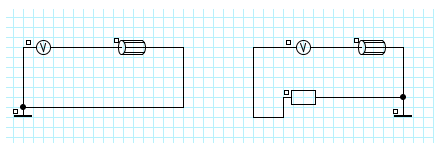
I made the geometry for a single-phase transformer on Flux2D. I know the values of the current and the voltage that I am supposed to have in the stator and the rotor during an open circuit test, and also the phase difference and the transformation ratio. And I would like to see if I get the same results with the software. The stator is on the left of the picture. On the right, there is the rotor with an infinite resistance. Since I know the transformation ratio, I know the value and the phase of the voltage to put in the software. But I don't know if it's the way to do on Flux2D. When you create the circuit, where do you indicate the mutual inductance between the rotor and stator ?
Thank you in advance!
Hi there,
To have a very large resistor in series with the stranded conductor that represents the secondary winding of the transformer is a valid method; you are doing the right way.
Now, regarding to the mutual inductance between the primary and the secondary winding, once that you estimate the voltage induced at the secondary just apply the transformation ratio to reflect the voltage magnitude from secondary to primary and divide the resultant by 2*PI*f*Im where Im will be the current RMS that you estimate at the primary winding circuit. That will get you a good estimate on the mutual inductance between primary and secondary.
Hope this comment helps!
Hi,
In Flux 3D supervisor example, there is an example about the transformers and different tests that you need to do. I think you can check this example (no load test) to see how we do it in Flux.
Best regards.