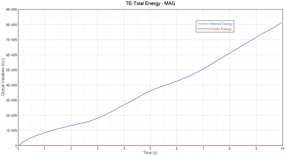
Both kinetic energy and internal energy are not consistence!!
Hello
As the relation between internal and kinetic energy are completely different, and I have observed during solving DM/M is not zero also. I think, my time step is less enough so, I set Tmin=1e-006, Tscale=0.9. How to adapt this kind of poblem in order to get the better results
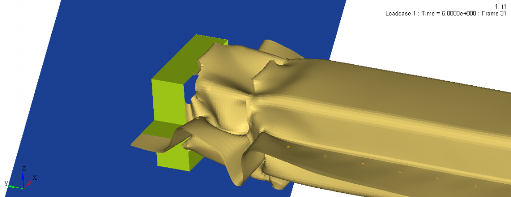
My model is composed of the deformable tube, rigid wall, solid spot weld and fixture (green color) as picture below. In this analysis, I used the symmetry condition (half part) and defined the impose velocity (10mm/s) constantly at the back side of the tube.
If you need more information please tell me, Thank you
Sincerely
Nut
Answers
-
Hi Nut,
While imposing a time step the best practice is to have less than 5% added mass (0.05) which can be monitored in the engine out file (DM/M).
The energy plot is a typical quasi static simulation plot.
We have a similar kind of tutorial in Help Menu, RD-3530: Buckling of a Tube using Half Tube Mesh. I recommend you to refer the same.
0 -
Hi
Thank your for your answer, as you said, I should only use the Tsacale= 0.9 and must set Tmin = 0.0 right?
Sincerely
Nut
0 -
Hi Nut,
If you are using Tmin as 0, that means no time step is imposed in the model and so no mass will be added in the model and the DM/M will remain zero.
But in case if you want to impose a time step, which controls the model from dropping time step, mass will be added but the Tmin should be an optimum value that the mass added in the model should be less than 5% (.05).
0 -
That mean, I have to define the best time step value for this anlysis that have both computational consumption and less mass error right?
So, i found that Tscale = 0.65 and Tmin=2.4e-7 both of this conduct to get 0.4 mass err ap[loximately.
Many thank for your suggestion
Sincerely
0 -
-
Hi Nut,
You are right, the time step value chosen should be an optimal one.
As a general note, although increasing Tmin value increases the computational speed considerably, care must be taken to see that a bound is put on the percentage of mass increase. It should not change the physics of the problem i.e. mass increase is allowed for deformable bodies but if applied to rigid bodies then results will be different than the original model. Hence always the mass error created should be very less.
0 -
CYCLE TIME TIME-STEP ELEMENT ERROR I-ENERGY K-ENERGY T K-ENERGY R EXT-WORK MAS.ERR
13000 0.3510E-02 0.2700E-06 NODE 7479 -13.6% 2225. 5549. 1314. 0.1051E+05 0.4830E-04
13100 0.3537E-02 0.2700E-06 NODE 7077 -13.2% 2180. 6311. 1133. 0.1108E+05 0.4830E-04
13200 0.3564E-02 0.2700E-06 NODE 7946 -12.8% 2045. 7183. 949.9 0.1167E+05 0.4830E-04
13300 0.3591E-02 0.2700E-06 NODE 7228 -12.2% 1837. 8116. 790.2 0.1224E+05 0.4830E-04
13400 0.3618E-02 0.2700E-06 NODE 7946 -11.7% 1789. 8851. 659.1 0.1279E+05 0.4830E-04
13500 0.3645E-02 0.2700E-06 NODE 7070 -11.2% 1761. 9446. 565.3 0.1326E+05 0.4830E-04
13600 0.3672E-02 0.2700E-06 NODE 7070 -10.9% 1636. 0.1005E+05 507.7 0.1368E+05 0.4830E-04
13700 0.3699E-02 0.2700E-06 NODE 7862 -10.6% 1445. 0.1060E+05 476.9 0.1401E+05 0.4830E-04
13800 0.3726E-02 0.2700E-06 NODE 7729 -10.6% 1395. 0.1081E+05 554.5 0.1427E+05 0.4830E-04
13900 0.3753E-02 0.2700E-06 NODE 7729 -10.8% 1482. 0.1064E+05 722.4 0.1440E+05 0.4830E-04
14000 0.3780E-02 0.2700E-06 NODE 7729 -11.0% 1466. 0.1062E+05 790.8 0.1447E+05 0.4830E-04
14100 0.3807E-02 0.2700E-06 NODE 7729 -11.3% 1634. 0.1035E+05 839.7 0.1446E+05 0.4830E-04
14200 0.3834E-02 0.2700E-06 NODE 7729 -11.8% 1933. 9907. 883.5 0.1442E+05 0.4830E-04
14300 0.3861E-02 0.2700E-06 NODE 7729 -12.2% 2034. 9602. 941.8 0.1432E+05 0.4831E-04
14400 0.3888E-02 0.2700E-06 NODE 7729 -12.4% 1895. 9528. 1011. 0.1420E+05 0.4831E-04
14500 0.3915E-02 0.2700E-06 NODE 7729 -12.6% 2008. 9199. 1088. 0.1407E+05 0.4831E-04
14600 0.3942E-02 0.2700E-06 NODE 7729 -12.8% 2236. 8741. 1161. 0.1392E+05 0.4831E-04
14700 0.3969E-02 0.2700E-06 NODE 7729 -13.0% 2228. 8520. 1233. 0.1378E+05 0.4831E-04
14800 0.3996E-02 0.2700E-06 NODE 7862 -13.2% 2351. 8195. 1286. 0.1364E+05 0.4831E-04
14900 0.4023E-02 0.2700E-06 NODE 7568 -13.4% 2514. 7862. 1323. 0.1351E+05 0.4831E-04
There is a fluctuation in kinetic energy and internal energy .Also Error % is also fluctuating. kindly suggest what could be the reason
0 -
assuming impact analysis, the energy and its error are consistent with the rebound phase:
-stored elastic strain (part of internal) energy gets released and is converted back into kinetic energy
-energy error is reduced while rebounding because the contact energy decreases (even more so if there is friction). Energy error can also be from hourglass energy (if under integrated elements are used) decreasing as the structure gets unloaded. Both Contact and Hourglass energies are dissipative (negative sign).
You can plot kinetic, internal, contact, hourglass and total energy in Hypergraph. Those variables are output by default and can be loaded in HG (file: runname_T01)>Global Variables>Y requests>MAG to plot.
For more details refer to the attached document (from free Radioss ebook)
0 -
You're welcome. Remaining time increases due to timestep drops. This could be because of deep contact penetrations or large element deformations (reducing characteristic element length). Timestep can be plotted as well in HyperGraph: runname_T01>Global Variables>time step>MAG.
0