The Siemens Community Catalyst program was co-created with our community to acknowledge technology leaders who consistently contribute to the Siemens Community. Nominations are accepted on a rolling basis.
Hi Folks,
Is there an example I can find for applying a base motion in the form of displacement to translationally constrained DOF's on a node using the SPC/SPCD card?
Thanks
Hi @IRA_EM
Please take a look at the attached tutorial in the documentation.
The only difference it that you're going to replace the DAREA for a SPCD (enforced displacement), and in the same node, you will create a SPC at the same DOF as the SPCD.
So, for example, for enforcing Y displacement in node 1000, you create a SPCD in DOF2, with value 1.0 for, and in the SPC load collector, you create a SPC = 0 in DOF 2, as well.
Unable to find an attachment - read this blog
Hi @IRA_EM Please take a look at the attached tutorial in the documentation. The only difference it that you're going to replace the DAREA for a SPCD (enforced displacement), and in the same node, you will create a SPC at the same DOF as the SPCD. So, for example, for enforcing Y displacement in node 1000, you create a SPCD in DOF2, with value 1.0 for, and in the SPC load collector, you create a SPC = 0 in DOF 2, as well.
@IRA_EM In addition to Adriano's answer, I think you will also need to specify Type as 'DISP' in RLOAD2 card for enforced displacement
Hi Adriano and Nathan,
Thanks for the tips. I now have the following problem.
The problem I have is how to combine these for assignment to the DLOAD entry in the subcase definition of Freq.resp (modal).
I thought I could combine the RLOAD1s into 1 load collector but therein lies the problem, as only one EXCITEID can be selected where in fact there are 3....
Any ideas are welcome
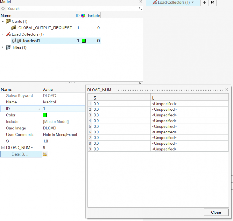
For combining any Dynamic Load, you need to use the load collector DLOAD and choose your 9 loads.
Don't forget to define the scalar factors S, and Sgloblal as well. (probably all 1.0)
Then, use this DLOAD combination in your LoadStep.
<?xml version="1.0" encoding="UTF-8"?>
Hi,
Clear but how does the solver know vi the DLOAd command which excitation ID to assign to the respective RLOAD1? There are 3 excitation points (3 SPCD) each with x,y and z.
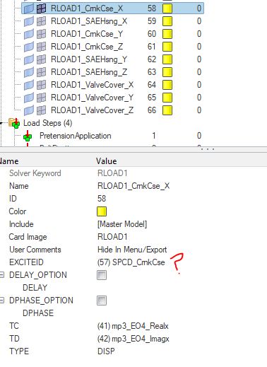
you will have 9 RLOAD cards, each one pointing to its own EXCITEID and TABLED1.
For X_point1, you will have a RLOAD1 pointing to the SPCD in X for point 1.
For Y_point1, you will have a RLOAD1 pointing to the SPCD in Y for point 1.
and so on..
in the end the DLOAD load collector will combine all you RLOAD1 cards into a single one, applying them all together.
This will be refereced in your LoadStep.
Don't forget to constraint with regular SPC each point and DOF where you apply the SPCDs.
Hi Adriano,
Great, that works.
Many thanks for your support.
BR
Ed
Mr @Adriano A. Koga
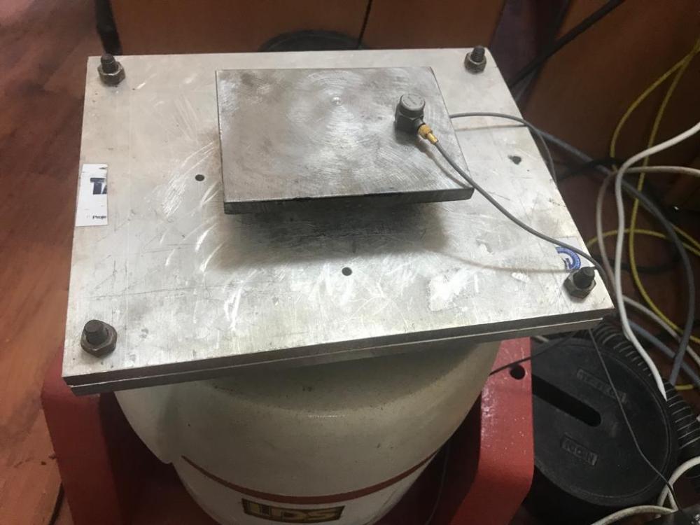
I am trying to model the following experimental system using the finite element method. this system was established to perform honeycomb specimen of base excitation test
I have a model can you help me
Do you have an error or something? Can you share the .out file?
This is a shaker, right?
Can you describe better your test input and desired output?
Do you have an error or something? Can you share the .out file? This is a shaker, right? Can you describe better your test input and desired output?
do you want to experimental data ?
I would like to reduce file size of the model for example I would like to avoid solid elements
I would like to reduce run time?
hi @durukanbdilek
i'm trying to understand better, physically, what are you trying to simulate here.
Can you describe better what are your test inputs, and desired responses?
First of all>
You're running Direct Frequency Response, which is very expensive computationally, as you're solving the equations coupled.
Usually we would use Modal Frequency Response for such problems. (Tutorials in OptiStruct help section)
I believe that your honeycomb modelling is ok, using shell elements.
The plate from the test jig doesn't need to ne solid, nor so refined.
You could use a simple shell model, and use some freeze contact (TIE) to keep the plate tied/glued to your honeycomb.
The plate would be the master, and your honeycomb the slaves.
There are a few tutorials in OptiStruct help, for contacts, if you're not familiar to it.
Another point is the output size.
You're requesting FREQ1 with 1Hz increment.
So all your results will be written for several frequencies, increasing memory requirements.
I would suggest you to take a look at FREQ4 (oly for Modal FRF). It takes a few points close to the natural frequencies of your model.
You could mix FREQ1 by 10Hz, and FREQ4 including 3 or 5 points.
Actually it depends a little bit on your frequencies. I believe in your model there are a lot of modes close, so maybe increasing the number of frequency points only close to these points.
Also for larger models (~1M nodes) using EIGRA instead of EIGRL it is a good approach. EIGRA uses AMSES solver, which applies sub-structuring for enhancing a lot the eigenvalue extraction, while introducing a small 'simplification'.
Speaking on eigenvalues, you're requesting only 15 first modes.
I'm not sure if this is enough for performing your analysis if you use Modal FRF.
Usually in these cases the rule of thumb is at least 1.5x the frequency of interest. So if you're interested in frequencies up to 200,Hz request EIGRL/EIGRA up to 300Hz. This is related to modal space for your solution.
.
Mr Koga I added you on facebook as a friend if you want talk
I would like to tell everything detailed
Mr Koga I added you on facebook as a friend if you want talk I would like to tell everything detailed
Why need Facebook ???
I wanted to get answers to the questions I asked instantly
I have trying to model this system for 6 months I create a new topic
but nobody interested
I found someone who could solve this problem
I will share detail of solution
hi @durukanbdilek i'm trying to understand better, physically, what are you trying to simulate here. Can you describe better what are your test inputs, and desired responses? First of all> You're running Direct Frequency Response, which is very expensive computationally, as you're solving the equations coupled. Usually we would use Modal Frequency Response for such problems. (Tutorials in OptiStruct help section) I believe that your honeycomb modelling is ok, using shell elements. The plate from the test jig doesn't need to ne solid, nor so refined. You could use a simple shell model, and use some freeze contact (TIE) to keep the plate tied/glued to your honeycomb. The plate would be the master, and your honeycomb the slaves. There are a few tutorials in OptiStruct help, for contacts, if you're not familiar to it. Another point is the output size. You're requesting FREQ1 with 1Hz increment. So all your results will be written for several frequencies, increasing memory requirements. I would suggest you to take a look at FREQ4 (oly for Modal FRF). It takes a few points close to the natural frequencies of your model. You could mix FREQ1 by 10Hz, and FREQ4 including 3 or 5 points. Actually it depends a little bit on your frequencies. I believe in your model there are a lot of modes close, so maybe increasing the number of frequency points only close to these points. Also for larger models (~1M nodes) using EIGRA instead of EIGRL it is a good approach. EIGRA uses AMSES solver, which applies sub-structuring for enhancing a lot the eigenvalue extraction, while introducing a small 'simplification'. Speaking on eigenvalues, you're requesting only 15 first modes. I'm not sure if this is enough for performing your analysis if you use Modal FRF. Usually in these cases the rule of thumb is at least 1.5x the frequency of interest. So if you're interested in frequencies up to 200,Hz request EIGRL/EIGRA up to 300Hz. This is related to modal space for your solution. https://community.altair.com/community?id=community_question&sys_id=524600b61b2bd0908017dc61ec4bcb67 .
I aim compare vibration isolation characteristic of the honeycomb specimen
so I preferred to calculate direct FRF, also @Rahul R suggested me that direct FRF is more availeble
With Direct FRF there's not much to do to enhance performance, as it needs to solver the equations coupled, for each frequency.
Anyway, you can try to reduce some freqnecies, if you already know what are your frequency range of interest, and save some time.
ok thank you, Mr Koga
I have some question marks in my head about modeling
there are a plate made from metallic material above honeycomb specimen
Should I model this rigidly?
looks like it is much stiffer than your specimen, so i would say it would be ok to model it as rigid.
I would say that if it is not rigid enough in the test, it would affect your test values.
the plate acts as a rigid mass, while specimen is deformable
Mr.Koga,
I used an adhesive between plate and specimen, also there are another rigid plate bottom the specimen
also specimen was glued to bottom plate how to model this stuation
as suggested before, TIE contact would do the work here, if you really want to add the plate (shell or solid).
TIE contact create a zero relative displacement condition between contact pairs.
I have a model in attachment
but this model do not agreed wit experimental data
first point would be to validate a modal analysis and check if frequencies are ok. How do they compare?
I'd say that if frequencies are not ok, then stiffness or mass are wrong.
look I added you on facebook I need your help emergency
i believe the forum is the best way to solve any question, and additionally the solution of your problem might be useful for others.
it would be nice for you to share here what are the differences that you found between FEA and tests.
1) normal modes are ok?
2) mass is ok?
3) what is the shaker input?
4) what are you measuring? acceleration? displacement?
in the model I shared first, four of mode frequencies were agreed with experimental results but experimantal test rig is not enough to determine mod shapes and I have not enough accelerometer
mass of real rigid plate and mass in numerical model are agreed
shaker input is acceration of .25 g
output is acceraiton
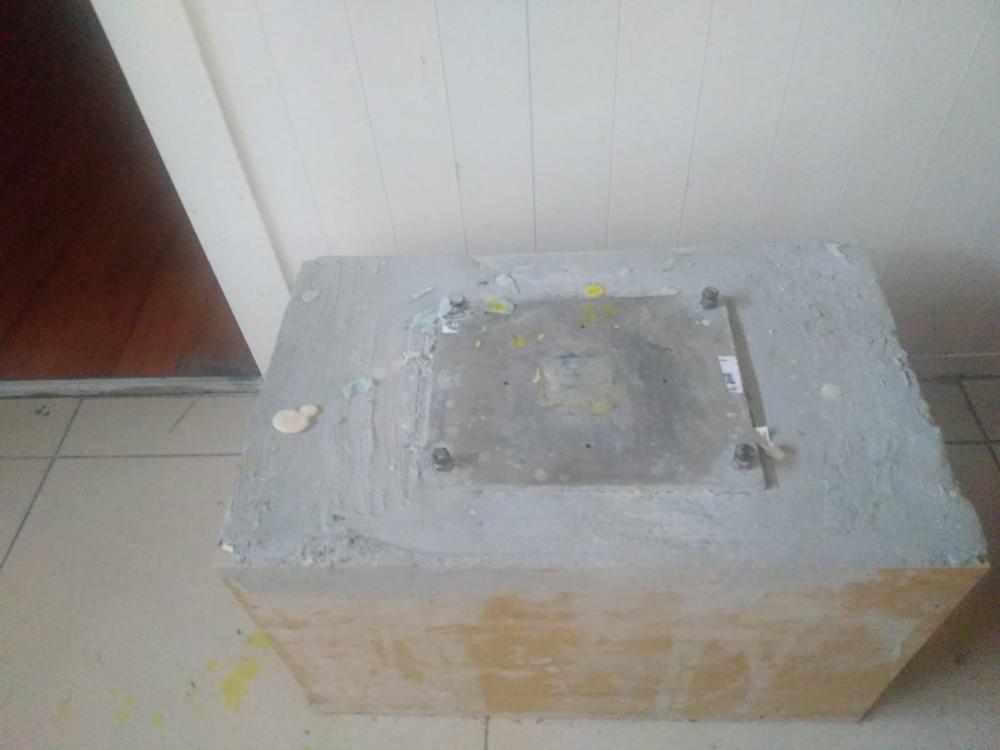
also impact hammer test was performed on this concrete
the honeycomb specimen with rigid plate was glued to the metal plate, which embedded to concrete using adhesive .
the results from this experiments were agreed to numerical results
ok. now it is a little bit more clear what you're testing.
now, what exactly is not fitting the test?
Is is the frequency response? Or the impact?
yes some frequencies of fem model were agreed with experimental results from this test system
in this test honeycomb specimen with rigid mass was bonded using an adhesive material and tests were performed with impact hammer
I assumed that bottom of the honeycomb is clamped I'm not sure if this is true or not.
do you have a table or graph comparing what is expected vs what you got? It would be helpful to have some visual results.
Does your model have higher frequencies than your test?
yes, but I interest range of 10-250 Hz
yes I have some results for this test